Index-1
Numbers
10BASE-T and 8-pin MJ Crossover Cable
Connection
B-7
10BASE-T and AUI selector switch
1-5
10BASE-T Ethernet Connector
B-4
10BASE-T Link LED
1-5
10BASE-T Port connection
1-5
8-pin MJ Ports
B-5
A
AUI Port 1-5
AUI Selection LED
1-5
B
Back Panel Components 1-6
Back panel features
1-6
C
Cables
Cabling the AUI 10BASE-T Port
Adapter
5-8
Cabling the AUI BNC Port Adapter
5-9
Cabling the AUI Fiber Port Adapter
5-7
Cabling the Ethernet AUI Adapters
5-7
Connecting 10BASE-T (UTP)
5-5
Connecting the Ethernet AUI Adapters
5-6
Connecting the Power Cable
5-10
Removing Cables
5-11
Removing the 10BASE-T (UTP) Cable
5-12
Removing the Power Cable
5-17
Cabling
10BASE-T Ethernet Connection
Requirements
4-6
Cables and Adapters for the DECserver
4-4
Maximum Cable Lengths for Data Rates
4-5
Maximum Communications Distances
4-5
Standard Ethernet Connection Requirements
4-6
Connecting
Serial Cables and Devices on the DECserver
4-3
the Ethernet Cables and Devices
4-2
Connector Pin Descriptions
B-2
Connectors
1-4
power
1-6
Crossover and Straight-Through Cable
Connections
B-6
D
DECserver
Back Panel Components
1-6
Front Panel Components
1-4
DECserver 716 and 732
Overview
1-2
Diagnosing Problems
A-2
Documentation
related documents
xv
E
EIA/TIA 423 (Asynchronous serial ports) 1-5
Ethernet Address (MAC Address Label)
1-5
Electrical Requirements C-4
Environmental Requirements C-5
Error Messages A-7
F
Features 1-3
Flash RAM Card
Flash RAM Slot
1-4
Flash RAM Slot
1-4
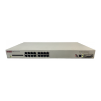
Front and Back Panel Components
1-4
Front Panel Components
1-4
I
Installing the Rack-Mounting Brackets to the
DECserver
2-3
L
LED
10BASE-T Link
1-5
AUI
1-5
Indicators 1-4
LNK
1-5
Network Activity LED
A-13
Power
1-4
LNK LED
1-5
Index