Front and Back Panel Components
1-4 Product Description
Front and Back Panel Components
The following sections describe the front and back panel components for both the
DECserver 716 and DECserver 732.
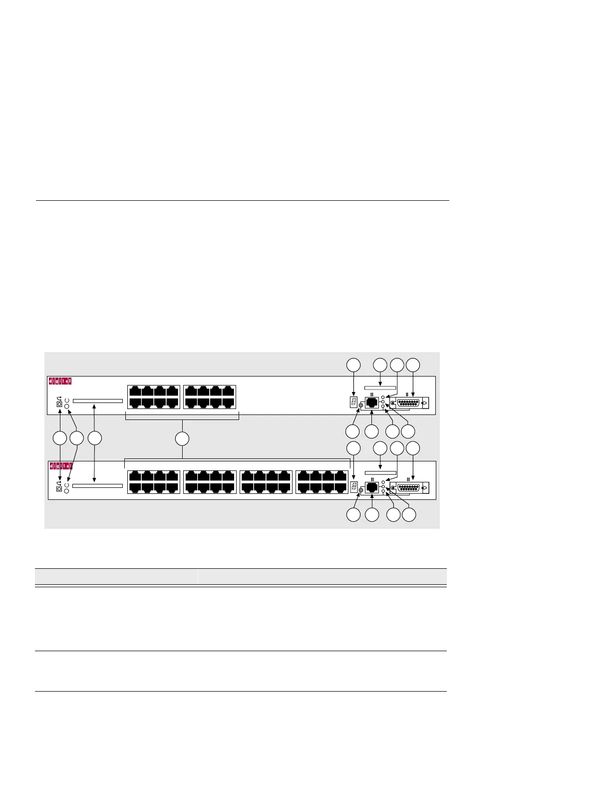
Front Panel Components
Table 1-1 describes the front panel components, and LEDs, that are illustrated in
Figure 1-1. For problem-solving information using the LEDs, refer to Appendix A,
Problem Solving.
Figure 1-1: Front Panel LEDs and Connectors
Table 1-1: Front Panel LEDs and Connector Descriptions
Item Name Description
1 Reset Switch On power up: press this switch until the System OK LED
blinks. This reloads the factory set parameters and all
customized parameters are lost. During Flash load,
pressing and holding the system reset switch will abort the
Flash RAM load and force a network boot.
2 System OK LED Lights when the DECserver has power.
On: DECserver has power.
Off: DECserver does not have power.
3 Flash RAM Slot Provides an opening to insert the optional Flash RAM
Card.
LNK
DECserver 732
2468
1357
10 12 14 16
9111315
18 20 22 24
17 19 21 23
26 28 30 32
25 27 29 31
LNK
DECserver 716
2468
1357
10 12 14 16
9111315
3505-03
5
6
7
8 9
12
11
5
6
7
8 9
12
11
1 3
4
10
10
2