– 21 –
Adjusting the horizontal image position
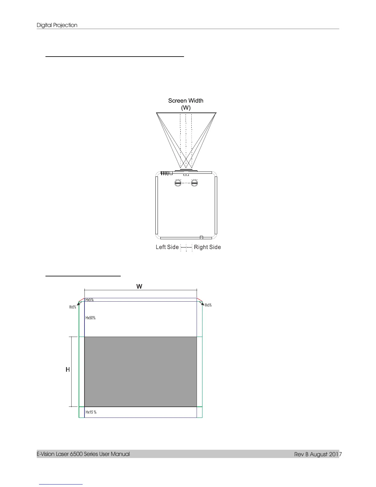
With the lens in the center position the horizontal image position can be adjusted to the left or right by up
to a maximum of 5% of the image width. Note that the maximum horizontal image height adjustment can
be limited by the vertical image position. For example it is not possible to achieve the maximum horizontal
image position if the vertical image position is at maximum. Please consult the Shift Range diagram below
for further clarification.
Shift Range Diagram
When W and H at 0% offset position
The max. H up shift=Hx55%
The max. H down shift=Hx15%
The max. W shift=Wx5%
When max. W shift is Wx5%
max. H shift=Hx50%
When max. H shift is Hx55%
 Loading...