12 www.dimplex.com
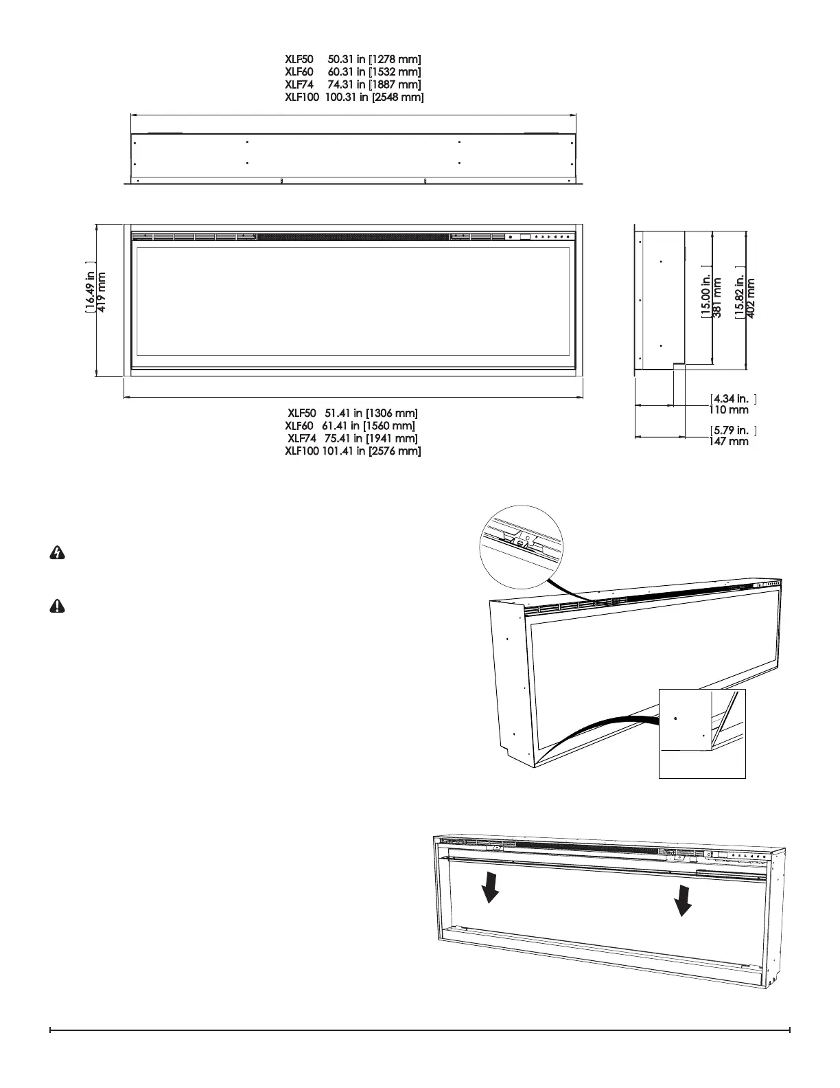
16.49 in
419 mm
15.82 in.
402 mm
15.00 in.
381 mm
5.79 in.
147 mm
4.34 in.
110 mm
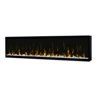
XLF50 50.31 in [1278 mm]
XLF60 60.31 in [1532 mm]
XLF74 74.31 in [1887 mm]
XLF100 100.31 in [2548 mm]
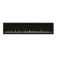
XLF50 51.41 in [1306 mm]
XLF60 61.41 in [1560 mm]
XLF74 75.41 in [1941 mm]
XLF100 101.41 in [2576 mm]
Preparation for Service
!
NOTE: All components are replaceable from the front
of the replace while the unit is mounted in the wall.
Tools Required: Philips head screwdriver
WARNING: Disconnect power before attempting any
maintenance or cleaning to reduce the risk of electric
shock or damage to persons.
CAUTION: If unit was operating prior to servicing allow
at least 10 minutes for lights and heating elements to cool
o to avoid accidental burning of skin.
!
NOTE: All instructions are created for replacement
of the XLF50 components and as a result the number of
screws may dier for the XLF60, XLF74, and XLF100.
1. Turn the breaker o at the electrical panel.
2. Remove the front glass assembly by removing the 2
screws (1 on the left and 1 on the right side, located
just inside the top front vent opening). These screws
secure the front glass panel to the inside of the re-
place. (Figure 4)
3. Lift the front glass assembly out of the unit and care-
fully place the glass assembly aside in a safe location.
4. Remove the decorative acrylic ember-bed pieces from
the media tray, which lies along the bottom of the inter-
ior partially reective glass. A medium sized container
such as a bucket or a box will be needed to keep the
acrylic ember-bed pieces together.
5. Attach the suction cup to the partially reective glass to
assist with removal (XLF74 & XLF100.)
6. Remove the 12 screws from the glass retaining brack-
et, starting on either end and working your way to the
Figure 5
Figure 4
Figure 3