15
8. If lenses are not present on the new LED strip follow
the following two steps before proceeding to step 9.
(Figure 8.)
I. Remove the lenses from the old LED strip (Figure 8.)
This will require some force when they are removed for
the rst time. It may be helpful to use a athead screw
driver to remove them,
II. Ax the lens to the new LED strip by aligning it over
the LED light and pressing down on it.
9. Install the new assembly and secure the LED strip to
the unit.
10. Reattach the wire connections.
11. Ensure that all wires are replaced in the same manner
as prior to the service.
12. Reassemble in the reverse order as above.
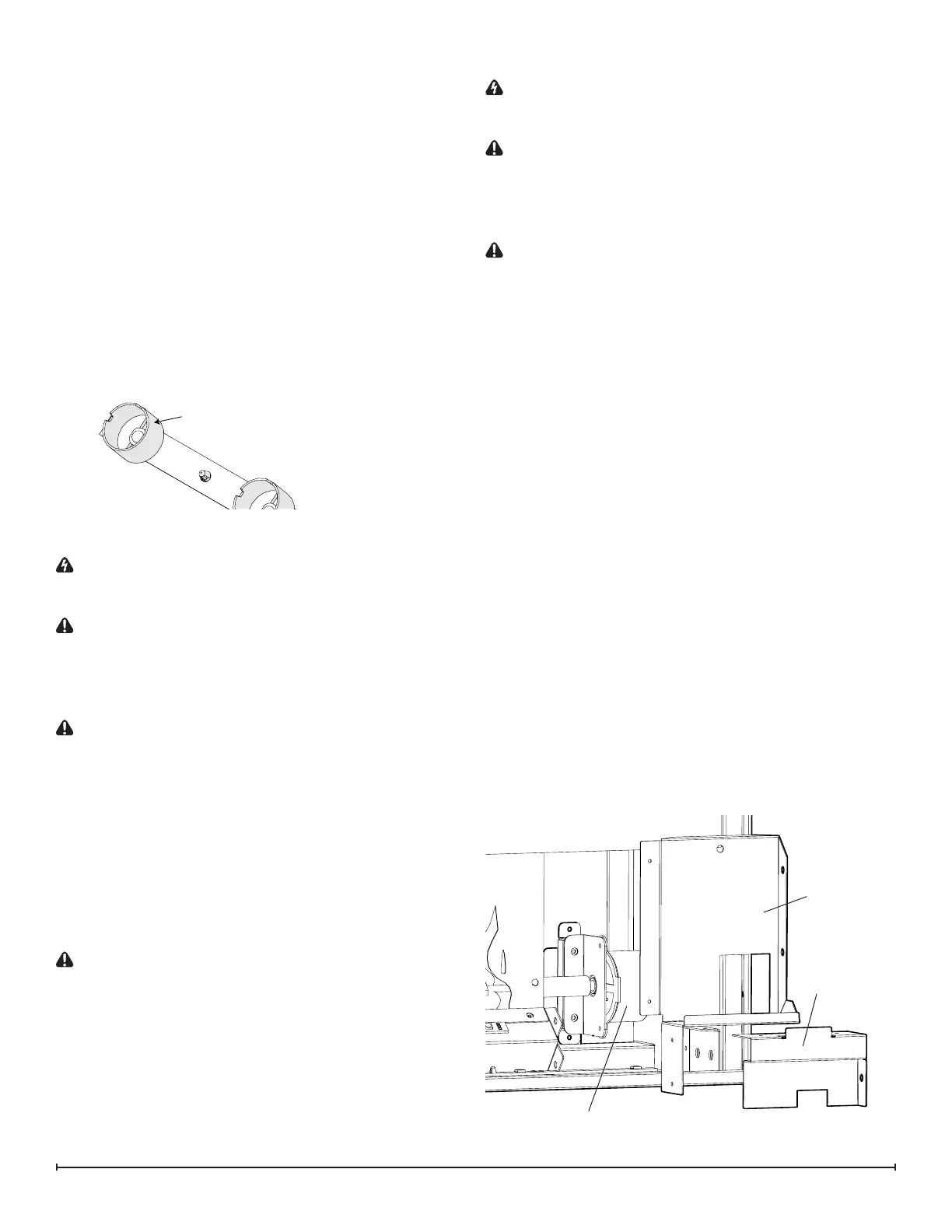
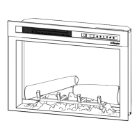
Upper Access
Cover
Flicker Assembly Replacement
WARNING: Disconnect power before attempting any
maintenance or cleaning to reduce the risk of electric
shock or damage to persons.
CAUTION: If unit was operating prior to servicing allow
at least 10 minutes for lights and heating elements to cool
o to avoid accidental burning of skin.
Tools required: Phillips head screwdriver
Wire cutters
CAUTION: Follow “Preparation for Service” instructions
before proceeding.
1. Remove the plastic media tray by removing the 4
screws: 2 on the left and 2 on the right of the tray.
(Figure 7)
2. Lift the plastic media tray out of the unit.
3. Remove the front panel by removing the 6 screws: 3 on
the left and 3 on the right of the tray.
4. Remove the 17 screws along the top of the ame panel
and gently remove. (Figure 6)
5. Gently pull the motor away from the icker rod.
CAUTION: When removing and replacing the icker mo-
tor try to keep any slight bending of the icker rod minimal
so as to not damage it. If icker rod is damaged, it should
be replaced to ensure proper operation.
6. Ensure that all wires are replaced in the same manner
as prior to the service.
7. Reassemble in the reverse order as above.
Flicker
Motor
Lower Access
Cover
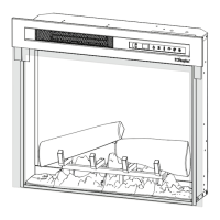
Lens
Flicker Motor Replacement
WARNING: Disconnect power before attempting any
maintenance or cleaning to reduce the risk of electric
shock or damage to persons.
CAUTION: If unit was operating prior to servicing allow
at least 10 minutes for lights and heating elements to cool
o to avoid accidental burning of skin.
Tools required: Phillips head screwdriver
Short handled Phillips head screwdriver
CAUTION: Follow “Preparation for Service” instructions
before proceeding.
1. Remove the plastic media tray by removing the 4
screws: 2 on the left and 2 on the right of the tray.
(Figure 7)
2. Lift the plastic media tray out of the unit.
3. Remove the front panel by removing the 6 screws: 3 on
the left and 3 on the right of the tray.
4. Remove the upper access cover located on the bottom
right hand side by removing the screws securing it to
the unit.
5. Remove the left most ame panel (gure 6), the 2 verti-
cal screws on the right hand side of the center ame
panel may need to be removed to easily pull the left
ame panel out.
6. Remove the icker motor mounting bracket from the
unit.
7. Remove the 2 screws holding the icker motor to the
mounting bracket. Gently pull the motor away from the
icker rod.
8. Remove the 2 screws holding the icker motor to the
mounting bracket. Gently pull the motor away from the
icker rod.
9. Trace the wiring up to the main control board and re-
place with new wires.
10. Properly orient the new icker motor onto the motor
bracket and re-attach with the 2 mounting screws.
Figure 8
Figure 9