13
middle, along the top of the opening, ensuring that
neither the bracket nor the partially reective glass falls
out of the unit. (Figure 5)
7. Gently lift the partially reective glass out of the unit
and set it aside in a safe place.
CAUTION: Partially Reective Glass is not tempered.
Do not bump or drop the Partially Reective Glass to avoid
breakage and personal injury.
8. Proceed to the instructions within this manual relating
to the repair being performed - see Table of Contents
for page number.
Main Control Board Replacement
WARNING: Disconnect power before attempting any
maintenance or cleaning to reduce the risk of electric
shock or damage to persons.
CAUTION: If unit was operating prior to servicing allow
at least 10 minutes for lights and heating elements to cool
o to avoid accidental burning of skin.
Tools required: Phillips head screwdriver
CAUTION: Follow “Preparation for Service” instructions
before proceeding.
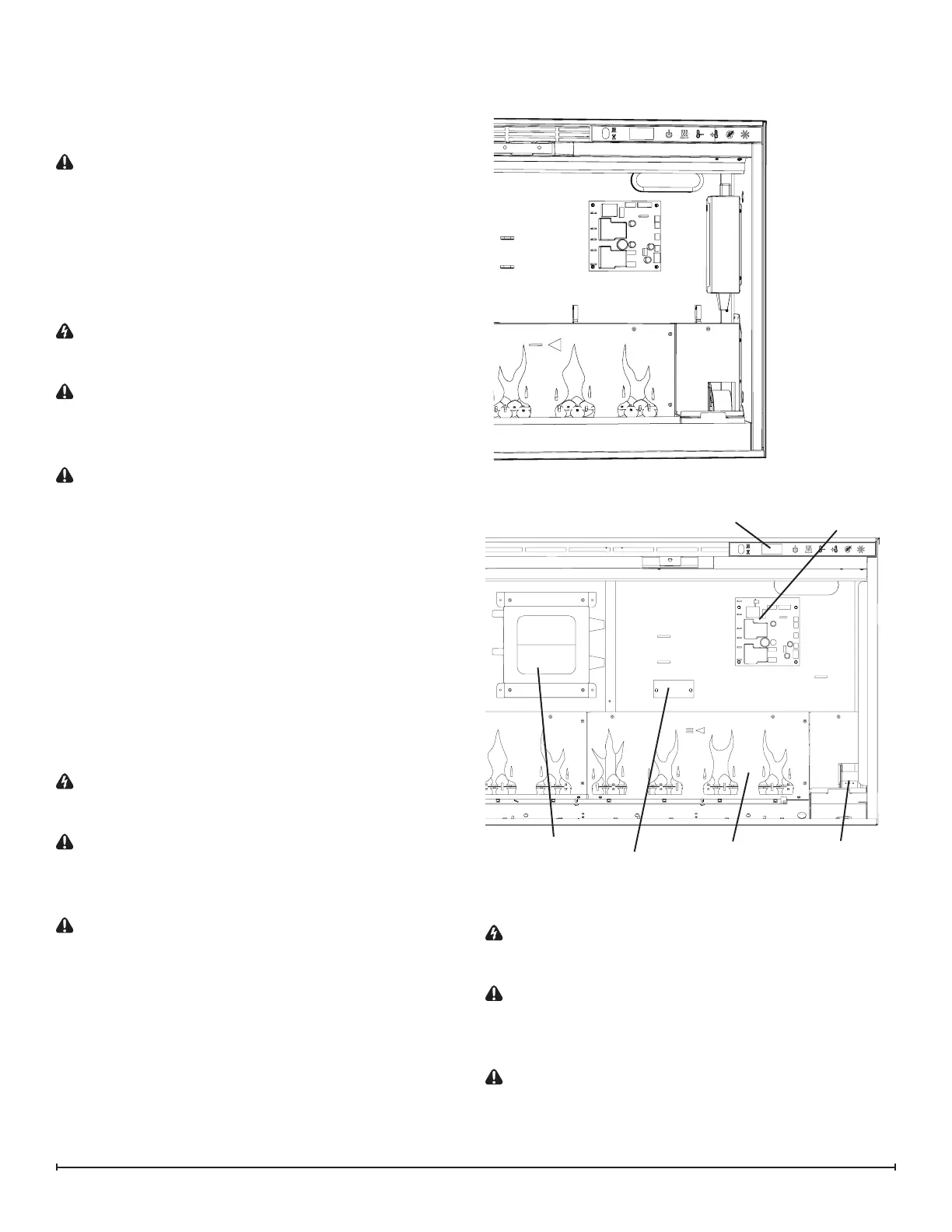
1. Locate the main control board. (Figure 6)
2. Transfer the connections from the old board to the new
board.
3. Remove the board, by removing the screw on each
corner.
4. Install the new board onto the unit.
5. Ensure that all wires are replaced in the same manner
as prior to the service.
6. Reassemble in the reverse order as above.
LED Power Distributor Replacement
(Only XLF74 & 100)
WARNING: Disconnect power before attempting any
maintenance or cleaning to reduce the risk of electric
shock or damage to persons.
CAUTION: If unit was operating prior to servicing allow
at least 10 minutes for lights and heating elements to cool
o to avoid accidental burning of skin.
Tools required: Phillips head screwdriver
CAUTION: Follow “Preparation for Service” instructions
before proceeding.
1. Locate the power distributor. (Figure 6)
2. Transfer the connections from the old board to the new
board.
3. Remove the board, by removing the screw on each
end.
4. Install the new board onto the unit.
5. Ensure that all wires are replaced in the same manner
as prior to the service.
6. Reassemble in the reverse order as above.
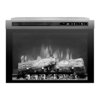
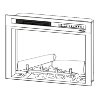
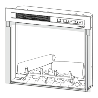
Figure 6
Flame Panel
Capacitive Controls
and Display
Flicker Motor
Main Control
Board
Power Supply
XLF50/XLF60
XLF74/100
LED Power
Distributor
Power Supply Replacement
WARNING: Disconnect power before attempting any
maintenance or cleaning to reduce the risk of electric
shock or damage to persons.
CAUTION: If unit was operating prior to servicing allow
at least 10 minutes for lights and heating elements to cool
o to avoid accidental burning of skin.
Tools required: Phillips head screwdriver
CAUTION: Follow “Preparation for Service” instructions
before proceeding.
1. Locate the power supply. (Figure 6)