18
© 2008 Directed Electronics All rights reserved.
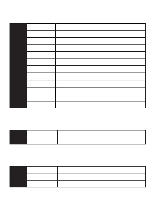
➤ Primary harness (H1)
H1/1
RED/WHITE (-) 200mA auxiliary channel
H1/2
RED (+) 12v Constant power input
H1/3
BROWN (+) Siren output
H1/4
YELLOW (+) Ignition input
H1/5
BLACK (-) Chassis ground connection
H1/6
VIOLET (+) Door trigger input
H1/7
BLUE (-) Instant trigger ( Zone1)
H1/8
GREEN (-) Door trigger input
H1/9
BLACK/WHITE (-) 200mA Domelight supervison output
H1/10
WHITE/BLUE (-) 200mA Channel 3 / 2nd unlock output
H1/11
WHITE (+) /(-) Light Flash output
H1/12
ORANGE (-) 500mA Ground When Armed
➤ Auxiliary harness (H2)
H2/1
LT. BLUE (-) Multiplex input (Zone4)
H2/2
BROWN (-) Horn Honk output
➤ Door lock harness (H3)
H3/1
BLUE (-) Unlock, (+) Lock output
H3/2
Not used
H3/3
GREEN (-) Lock, (+) Unlock output
 Loading...