13
© 2008 Directed Electronics. All rights reserved.
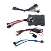
There are three harness connections relative to remote start function, including
the heavy gauge and input and output harnesses.
¢Heavy gauge remote start, (H3) 8-pin connector
H3/1
PINK (+) IGNITION 1 INPUT/OUTPUT
H3/2
RED/WHITE (+) FUSED (30A) IGNITION 2 / FLEX RELAY INPUT 87
H3/3
ORANGE ACCESSORY OUTPUT
H3/4
VIOLET STARTER OUTPUT
H3/5
RED (+) FUSED (30A) IGNITION 1 INPUT
H3/6
PINK/WHITE IGNITION 2 / FLEX RELAY OUTPUT 30
H3/7
PINK/BLACK FLEX RELAY INPUT 87A key side (if required) of FLEX
RELAY
H3/8
RED/BLACK (+) FUSED (30A) ACCESSORY/STARTER INPUT
¢Remote start input, 5-pin connector
1
BLACK/WHITE (-) NEUTRAL SAFETY SWITCH INPUT
2
VIOLET/WHITE TACHOMETER INPUT
3
BROWN (+) BRAKE SHUTDOWN INPUT
4
GRAY N/O or N/C (-) HOOD PIN SWITCH INPUT
5
BLUE/WHITE (-) 200 mA 2ND STATUS/REAR DEFOGGER OUTPUT