36
© 2008 Directed Electronics. All rights reserved.
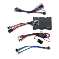
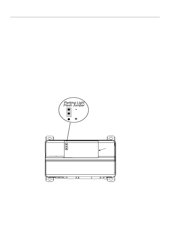
Setting the light flash polarity
Light flash (+) / (-) polarity
The internal fuse is used to determine the light flash output. In the (+) position, the
onboard relay will output (+)12V on the WHITE wire, H1/11. In the (-) position,
the on-board relay will supply a (-) output When wiring into a multiplex circuit,
you can replace the fuse with a resistor (paying attention to the polarity setting).
(Refer to diagram on p. 16, H1/4 White/ Brown wire description).
Note:
For parking light circuits that draw 10 amps or more, the internal jumper
must be switched to a (-) light flash output. P/N 8617 or a standard automotive
SPDT relay must be used on the H1/11 light flash output harness wire.
Access door
(Light Flash Fuse Jumper is under
access door - use needle nose pliers to
change fuse position)