EasyManuals Logo

Directed Electronics Viper 5501 Installation Guide

Directed Electronics Viper 5501
64 pages
To Next Page IconTo Next Page
To Previous Page IconTo Previous Page
Page #14 background imageLoading...
Page #14 background image
14
© 2008 Directed Electronics. All rights reserved.
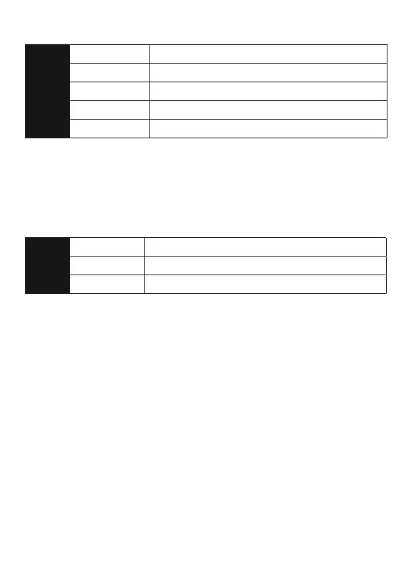
¢Remote start auxiliary output, 5-pin
1
PINK/WHITE (-) 200mA FLEX RELAY CONTROL OUTPUT
2
ORANGE (-) 200mA ACCESSORY OUTPUT
3
VIOLET (-) 200mA STARTER OUTPUT
4
PINK (-) 200mA IGNITION 1 OUTPUT
5
BLUE (-) 200mA STATUS OUTPUT
Note: Wires 1 - 4 on the remote auxiliary outputs are wired to the (-) triggers for
the onboard remote start relays and are not diode isolated. If connecting these
wires directly to the vehicle you must place a 1-amp diode in line to prevent
feedback from the vehicle.
¢Door lock harness, 3-pin connector
1
BLUE (+) LOCK (-) UNLOCK OUTPUT
2
EMPTY NOT USED
3
GREEN (-) LOCK (+) UNLOCK OUTPUT

Other manuals for Directed Electronics Viper 5501

Questions and Answers:

Question and Answer IconNeed help?

Do you have a question about the Directed Electronics Viper 5501 and is the answer not in the manual?

Directed Electronics Viper 5501 Specifications

General IconGeneral
BrandDirected Electronics
ModelViper 5501
CategoryRemote Starter
LanguageEnglish

Related product manuals