EasyManua.ls Logo

Directed DS4+ - User Manual

Directed DS4+
62 pages
Print Icon
To Next Page IconTo Next Page
Loading...
FORD6
INSTALLATION GUIDE
This product is intended for installation by a professional installer only! Attempts to install this
product by a person other than a trained professional may result in severe damage to a vehicle’s
electrical system and components.
2017-12-13
© 2017 Directed, Vista CA
DS4+
Designed by Installers for Installers

Questions and Answers

  • C
    christierodriguezSep 15, 2025
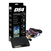
    Why Directed DS4+ Automobile Accessories OBDII feature is not supported?
    • A
      Alejandro WalkerSep 15, 2025
      The diagnostic data bus was not detected, therefore the SmartStart features will be limited in your Directed Automobile Accessories.
  • T
    Tiffany BarnettSep 15, 2025
    Why Directed DS4+ PTS shutdown error?
    • A
      Alan TuckerSep 15, 2025
      The PTS output from the Directed Automobile Accessories module was not activated due to safety protection.
  • J
    jasoncarrilloSep 15, 2025
    What to do if Directed Automobile Accessories CAN1 not detected?
    • K
      Kevin McneilSep 15, 2025
      Check the CAN1 Tan and Tan/Black wire connections. Wake up the data bus by turning the ignition on and try again. If your installation does not require this connection, skip this step by pressing the programming button 5 times.
  • J
    Jennifer DoyleSep 15, 2025
    What to do if Directed DS4+ CAN2 not detected?
    • M
      Morgan SanchezSep 15, 2025
      Check the CAN2 Orange/Green and Orange/Brown wire connections. Wake up the data bus by turning the ignition on and try again. If your installation does not require this connection, skip this step by pressing the programming button 5 times.
  • D
    Debra GarciaSep 15, 2025
    What to do if Directed DS4+ Automobile Accessories J1850 not detected?
    • S
      Stacey CookeSep 15, 2025
      Check the J1850 wire connection. Wake up the data bus by turning the ignition on and try again.
  • B
    Briana McdonaldSep 16, 2025
    What does 'Waiting to begin the programming sequence' mean for Directed DS4+, and how to solve it?
    • A
      Adam McdonaldSep 16, 2025
      This indicates that the programming sequence is not starting. To resolve this, ensure you are following the correct programming procedure.
  • W
    William HillSep 16, 2025
    What does it mean 'Initialization failed' for Directed DS4+?
    • M
      melissanobleSep 16, 2025
      Reset the module and complete the programming again. If the issue persists, please contact Technical Support.
  • C
    Christopher AdamsSep 16, 2025
    What does 'Bypass processing error' mean for Directed Automobile Accessories?
    • X
      xbondSep 16, 2025
      The bypass calculation failed. Reset the module and try again. If the condition persists, please contact Technical Support.
  • R
    Rhonda MillerSep 16, 2025
    Why Directed Automobile Accessories transponder functions were skipped?
    • M
      Malik HayesSep 16, 2025
      If compatible, when the RXT mode is not desired or convenience features are needed, please reset and reprogram the module.
  • K
    Karen PayneSep 16, 2025
    What does it mean 'Bypass and CAN were skipped' in Directed DS4+ Automobile Accessories?
    • M
      martinjefferySep 16, 2025
      This means that the programming button was pressed 5 times to skip bypass and 5 times to skip the CAN.

Summary

Warning! Safety first

Wiring connections

Installation Diagrams and Types

Type 1 with T-Harness (THFON1)

Installation diagram and details for Type 1 with T-Harness.

Type 2 with T-Harness (THFON1)

Installation diagram and details for Type 2 with T-Harness.

Type 3

Installation diagram and details for Type 3.

Type 5 with T-Harness (THFON1)

Installation diagram and details for Type 5 with T-Harness.

Type 8

Installation diagram and details for Type 8.

Vehicle wiring reference chart

Configuring the System

Module Programming - Using 2 Keys

Module Programming - 1-Key with Key2 GO

LED Diagnostics and Troubleshooting

Module Programming Indicators

LED indicators for module programming states and errors.

Analog Error Code Indicators

Troubleshooting analog feature configuration errors via LED.

Module Reset Procedures

Soft Reset Procedure

Resets programming steps without affecting firmware.

Hard Reset Procedure

Reverts firmware to default settings, requiring reconfiguration.

Tachometer Setup

Initializing Virtual Tach

Programming Virtual Tach for starter motor control during remote start.

SmartStart System Compatibility

Directed DS4+ Specifications

General IconGeneral
BrandDirected
ModelDS4+
CategoryAutomobile Accessories
LanguageEnglish

Related product manuals