B
beardlindaSep 15, 2025
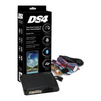
What to do if Directed DS4+ Automobile Accessories has DEI feature error?
- KKevin MyersSep 15, 2025
Please contact Technical Support if you encounter a DEI feature error with your Directed Automobile Accessories.
What to do if Directed DS4+ Automobile Accessories has DEI feature error?
Please contact Technical Support if you encounter a DEI feature error with your Directed Automobile Accessories.
What to do if ISO 2 is not detected on Directed Automobile Electronics?
If the Orange/Black wire did not detect the expected signal for the Directed Automobile Electronics, refer to “Installation (wiring diagrams & vehicle wiring reference charts)” to check the connections.
What to do if ISO 1 is not detected on Directed Automobile Electronics?
If the Yellow/Black wire did not detect the expected signal for the Directed Automobile Electronics, refer to “Installation (wiring diagrams & vehicle wiring reference charts)” to check the connections.
How to troubleshoot Directed DS4+ module with no power?
First, check that the D2D harness is properly connected. Then, verify that there is 12 Volts present between the red and black wires. If the voltage is correct, the Directed module might be defective.
What to do if MUX is not detected on Directed DS4+ Automobile Accessories?
The Violet/Green or Violet/Brown wire did not detect the expected voltage value. Check the connections.
Why speed was detected on Directed Automobile Accessories?
The vehicle was detected as moving, which prevents the system from shutting it down.
What to do if Directed Remote Starter is waiting to begin the programming sequence?
Make sure that you are following the correct programming procedure.
What to do if there is a bypass processing error on Directed Control Unit?
Reset the module and try again. If the condition persists, please contact Technical Support.
What does DEI feature error mean on my Directed Remote Starter?
A feature config file mismatch was detected.
What to do if Directed Automobile Electronics initialization failed?
If the Directed Automobile Electronics initialization failed, reset the module and complete the programming again. If the issue persists, please contact Technical Support.
Installation diagram and details for Type 1 with T-Harness.
Installation diagram and details for Type 2 with T-Harness.
Installation diagram and details for Type 3.
Installation diagram and details for Type 5 with T-Harness.
Installation diagram and details for Type 8.
LED indicators for module programming states and errors.
Troubleshooting analog feature configuration errors via LED.
Resets programming steps without affecting firmware.
Reverts firmware to default settings, requiring reconfiguration.
Programming Virtual Tach for starter motor control during remote start.
| Brand | Directed |
|---|---|
| Model | DS4+ |
| Category | Automobile Accessories |
| Language | English |