Rev.: 20 708115
Platform: DBALL2
Firmware TL6:
© 201 Directed.7 All rights reserved.
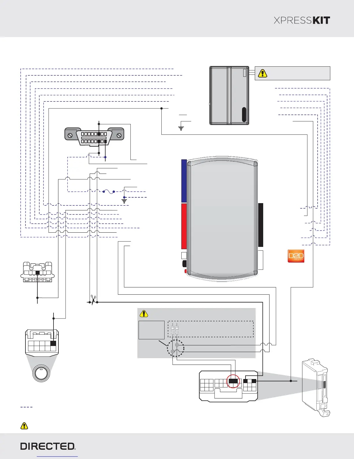
Main
Body
ECU
ENGINE
START
STOP
Push-to-Start
(black 10-pin onnector)c
(-) Trunk Status Input
[1] ( ) T Status InputAC ach
(-) Door Status Input
(-) E-Brake Status Input
(+) 12V Input
(-) Ground
(+) Brake Input
(-) Hood Status Input
HS CAN High: 3Tan/Black:
HS CAN Low: 4Tan:
(-) Ground: 12Brown :/Red
(-) Output:SLP 11Yellow :/Red
(+) 12V :Input 13Red:
(-) Ground: 14Black:
(+) Brake Output: Gray: 6
(-) Hood Status Output: 9Violet/Brown:
Immo Data 1: Yellow/Black: 10
(+) Ignition Status Output: Gray/Black: 7
Immo Data 2: Orange/Black: 11
(-) Push-to-Start Output: Green/Black: 2
(-) Door Status Output: Green/White: 3
(-) Trunk Status Output: Red/Black: 4
[1] ( ) Tach Output: 5AC Violet/White:
(-) E-Brake : 1Status Black/White:
Diagnostic Connector OBDII
(connector side view)
(+) Ignition Input/Output
Remote
Starter
(-) (Status)GWR
(-) OutputLock
(+) Starter Output
(-) OutputUnlock
(-) Trunk Output
1: (-) Lock InputGreen:
2: (-) Unlock InputBlue:
3: (-) Trunk InputRed/White:
8: (+) Starter InputViolet:
10: Blue/White:
(-) (Status) InputGWR
9: (+) Ignition InputPink:
18
169
2345
109876
1
(-) PTS:
Black, pin 1
12
3
5
4
7
6
(+) :12V
Green, pin 16
(-) SLP:
Green,
pin 4
(+) 12V
Steering Lock
(black 7-pin
nnector)co
Not required in D2D mode.
Page 14
Installation Type 5
10
RF
Prog utton. B
LED
4
2
P#: 2D65XKD
TX
(-) Ground
RX
(+)12V
2DBALL
14
12
Unless specified otherwise, all connectors are displayed from the wire side, with the exception of the diagnostic connector.OBDII
[1] Tach wire is an optional connection required on some remote starters,
which do not support a tach signal in D2D.
Autolight Interrupt (veh.side): 9Orange/Yellow:
Autolight Interrupt (conn.side): 8Yellow:
Fuse 7.5A
(-) Parking Lights Output
13
1
7
19
3
9
21 30
6
4
28
2625
8
20
2
10 12
2223
24
11
14
15
27
181716
5
29
Body ECU
(white 30-pin
Connector)
(-) Autolight:
pViolet, in 28
(-) Parking lights:
p30White, in
Solder onto a diode, cut away the unneeded
portion, and then insert into empty pin as shown.
Diodes
Solder the
wire to secure
it on the metal
pin.
This part can be removed because
only the metal pin is needed to
secure the contact in the empty pin.
BTX: pin 25
BRX:
pin 26
Do not connect these wires:
accessory ignition starter,,
from the remote starter to the vehicle.
HS CAN High pin 6: Red,
HS CAN Low:
White, pin 14