Rev.: 20 708115
Platform: DBALL2
Firmware TL6:
© 201 Directed.7 All rights reserved.
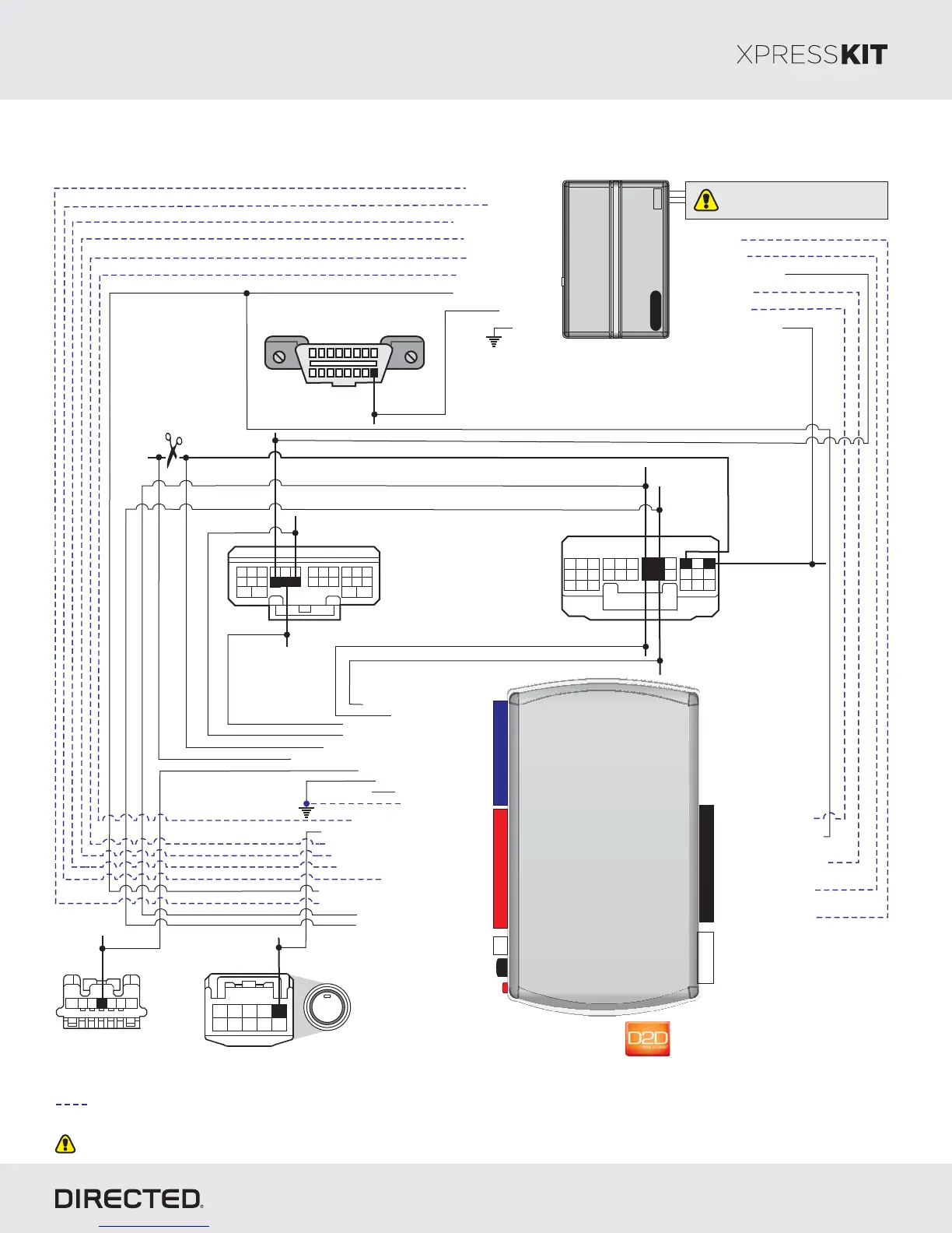
Not required in D2D mode.
Body ECU
(white30-pin
onnector)c
1
7
19
3
9
21 30
6
4
28
2625
8
20
2
10 12
2223
24
11
1413 15
27
181716
5
29
12
3
5
4
7
6
Steering Lock
(Black 7-pin
onnector)c
HS CAN 1 High: 3Tan/Black:
HS CAN 2 : 6Low Orange Brown/:
HS CAN 2 High: 5Orange Green/:
HS CAN 1 Low: 4Tan:
(-) Ground: 12Brown :/Red
(-) Output:SLP 11Yellow :/Red
(+) 12V :Input 13Red:
(-) Ground: 14Black:
(+) Brake Output: Gray: 6
(-) Hood Status Output: 9Violet/Brown:
Immo Data 1: Yellow/Black: 10
(+) Ignition Status Output: Gray/Black: 7
Immo Data 2: Orange/Black: 11
(-) Push-to-Start Output: Green/Black: 2
(-) Door Status Output: Green/White: 3
(-) Trunk Status Output: Red/Black: 4
[1] ( ) Tach Output: 5AC Violet/White:
(-) E-Brake : 1Status Black/White:
Autolight Interrupt (veh.side): 9Orange/Yellow:
Autolight Interrupt (conn.side): 8Yellow:
P#: 2D65XKD
Installation Type 8
Page 21
Unless specified otherwise, all connectors are displayed from the wire side, with the exception of the diagnostic connector.OBDII
[1] Tach wire is an optional connection required on some remote starters, which do not support a tach signal in D2D.
10
RF
Prog utton. B
LED
4
14
12
2
2DBALL
10
RF
Prog utton. B
LED
4
14
12
2
2DBALL
TX
(-) Ground
RX
(+)12V
1: (-) Lock InputGreen:
2: (-) Unlock InputBlue:
8: (+) Starter InputViolet:
10: Blue/White:
(-) (Status) InputGWR
9: (+) Ignition InputPink:
(-) Trunk Status Input
( ) T Status InputAC ach
(-) Door Status Input
(-) E-Brake Status Input
Remote
Starter
(-) (Status)GWR
(-) OutputLock
(+) Starter Output
(-) OutputUnlock
(-) Trunk OutputRelease
(-) Ground
(+) Brake Input
(-) Hood Status Input
(+) Ignition Input/Output
(+) 12V Input
(+) 12V
[1]
(-) Parking Lights Output
(-) SLP:
Blue, pin 4
BRX: Green
or White,
pin 26
Autolight Interrupt:
in 28Red, p
HS CAN High 1:
Red, pin 14
HS CAN Low 1:
Gray or White, pin 13
BTX:
pin 25Black,
18
169
(+) 12V: Black or White,
p n 16i
(-) Parking lights:
Black, p n 30i
ENGINE
START
STOP
Push-to-Start
(black 10-pin onnector)c
2345
109876
1
(-) :PTS
pin 1Green,
Do not connect these wires:
accessory ignition starter,,
from the remote starter to the vehicle.
Diagnostic Connector OBDII
(connector side view)
Body ECU
(white 28-pin
onnector)c
1
2
34
17
28
16
5
8
18 19
2223
10976
25 2724 2623
13 1512 1411
HS CAN 2 Low: pin 10Gray,
HS CAN 2 High: pin 9Red,
20
( Trunk Release-) : pin 8Yellow,