16
IP2371EN
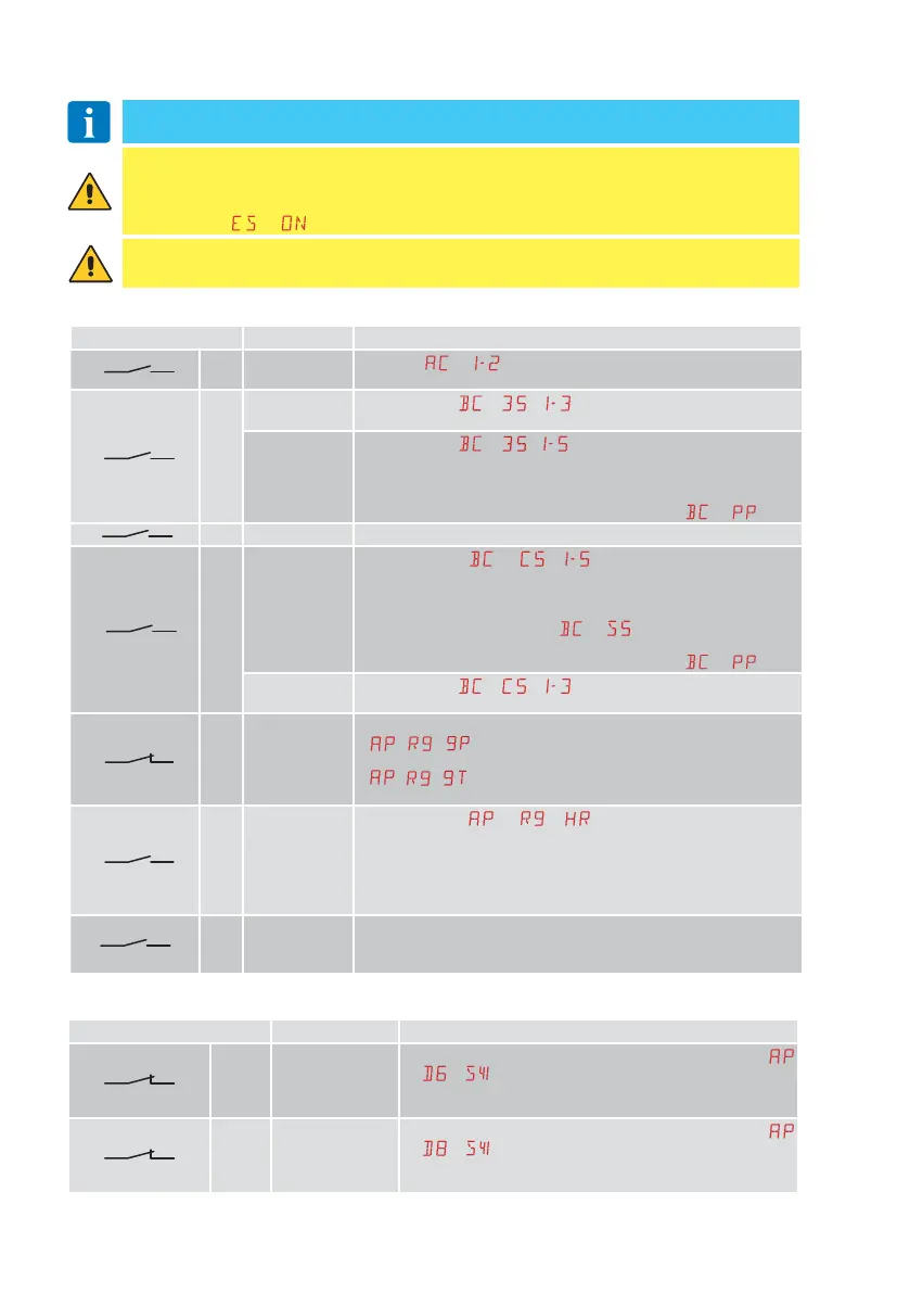
4.1 Command inputs
Command Function Description
30
2 NO
AUTOMATIC
CLOSURE
Selecting
→ , the permanent closed state of the contact
enables automatic closing.
30
3 NO
OPENING
When selecting
→ → , the closure of the contact activates
an opening operation.
STEP-BY-
STEP
When selecting
→ → , the closure of the contact activates
a sequential opening or closing operation: opening-stop-clos-
ing-opening.
The “opening-stop-closing-opening” sequence can be changed to
“opening-stop-closing-stop-opening” by selecting
→ .
30
4 NO CLOSURE Closing of the contact activates a closing operation.
30
5 NO
STEP-BY-
STEP
When selecting
→ → , closing the contact starts a
sequential opening or closing operation: opening-stop-clos-
ing-opening.
WARNING: if automatic closure is enabled, the duration of the stop
can be defined by selecting
→ .
The “opening-stop-closing-opening” sequence can be changed to
“opening-stop-closing-stop-opening” by selecting
→ .
OPENING
When selecting
→ → , the closure of the contact activates
an opening operation.
30
9
NC STOP
The opening of the safety contact causes the current operation to stop.
If
- = ,automatic closure is disabled when contact 30-9
recloses.
If
- = ,automatic closure remains enabled when contact
30-9 recloses.
30 9 NO
“HOLD-TO-
RUN”
OPERATION
When selecting → → , the opening of contact 30-9
enables the "operator present" function:
- opening with operator present 30-3
- closure with operator present 30-4
NOTE: any safety devices, automatic closure and plug-in board in
the AUX slot are all disabled.
30
20 NO
PARTIAL
OPENING
The closure of the contact activates a partial opening operation.
Once the automation stops, the partial opening control performs the
opposite operation to the one performed before the stop.
4. Commands and safety devices
WARNING: terminal 30 (common positive for commands) has the same functions as
terminal 1 and for this reason, the commands visible on the display are indicated with
1-5, 1-3, 1-4, etc. However, unlike terminal 1, it is also active when the control panel
is in stand by
→ .
You are advised to read paragraph 11 for all the details about the possible adjustments.
4.2 Safety inputs
Command Function Description
1 6
NC SAFETY STOP
For safety devices with self-test input: When selecting
→
→ , connect the output contact of the safety de-
vice to terminals 1-6 on the control panel (in series with the
photocell output contact, if installed).
1
8
NC
REVERSAL
SAFETY DEVICE
For safety devices with self-test input: When selecting
→
→ , connect the output contact of the safety de-
vice to terminals 1-8 on the control panel (in series with the
photocell output contact, if installed).
WARNING: make a jumper for all NC contacts if not used, or deactivate them via the relative
menu.
Terminals with the same number are equal.