BA FlexxPump 125 - 24 V_20181121_EN de 201811 25
External Control
7. External Control
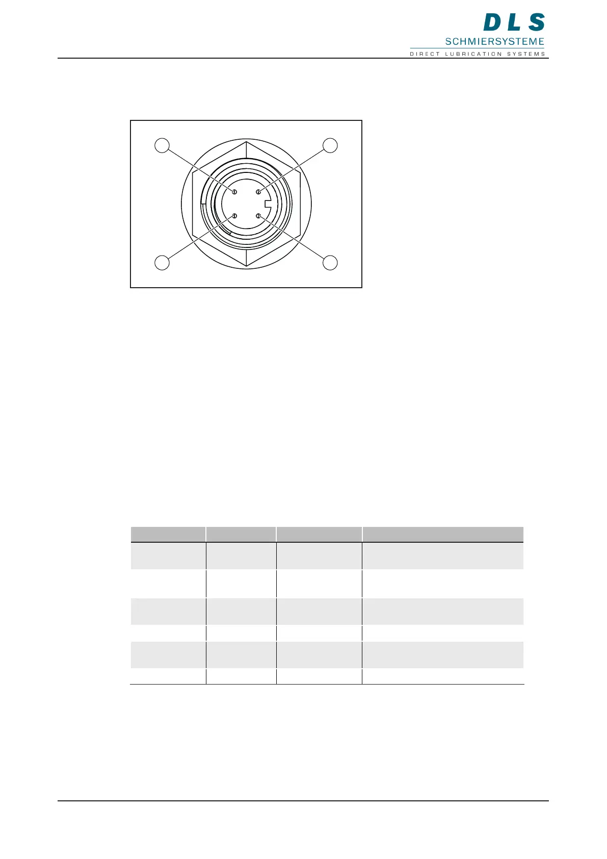
M12x1 connection for external control
1
2
4
3
1. PIN 1, +24 V DC
2. PIN 2, control signals
3. PIN 3, ground
4. PIN 4, output signals
The FlexxPump 125 has a 4-pin connector for connecting to a plant controller (external
control of the FlexxPump 125). This is on the bottom of the housing.
7.1 Control Signals (PIN 2)
This chapter describes the signals for controlling the FlexxPump 125 by an external
controller. The values and settings refer to the factory settings of the FlexxPump 125, see
5.1 Adjustable Parameters.
The FlexxPump 125 is controlled exclusively by high level signals at PIN 2.
7.1.1. Overview of Control Signals
The FlexxPump 125 provides the following predened control signals (input signals).
Signal length Designation Function Beschreibung
2sec high Signal 2sec 1 pump stroke Execution of a single lubrication
process
3sec high Signal 3sec 2 pump strokes Execution of two consecutive
lubrication processes
4sec high Signal 4sec C pump strokes Lubrication processes according
to parameter C setting
6sec high Signal 5sec 40 pump strokes Venting or lling function
10sec high Signal 10sec Error
acknowledgment
Acknowledgment of error
messages
12sec high Signal 12sec 40 pump strokes Venting or lling function