10 734N Installation and Programming Guide | Digital Monitoring Products, Inc.
Terminals 5-9 connect grounded zones 1 through 3. These zones have a grounded side and
cannot be used for fire-initiating devices. Zones 2 and 3 can also be used for access control with
Zone 2 providing a bypass option and Zone 3 providing Request to Exit functionality. Zone 4
terminals provide a non-powered Class B, Style A zone. Use the supplied DMP Model 311 1K Ohm
End-of-Line resistors on each zone. Refer to the panel programming guide for programming
instructions. See Figure 9 for more information on wiring the zone terminals.
Auxiliary Outputs 1 & 2
The 734N controls Auxiliary Outputs 1 and 2 when the Activate Zone 2 Bypass programming option
is enabled and the Zone 2 Bypass Time is set. When the door contact (Zone 2) is opened while the
door strike is activated, the Zone 2 Bypass Time starts. If the door has not closed at the end of the
timer, Aux Output 1 is turned on and the timer starts again. If the door is still open at the end of the
second timer, Aux Output 2 is turned on. Aux Outputs 1 and 2 turn o when the door contact is
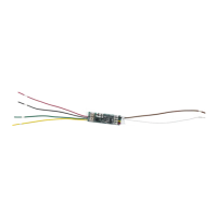
closed. Use the Model 431 Relay Harness for connection of Output 1 and Output 2.
5
WIRE THE ZONE TERMINALS