Digital Monitoring Products, Inc. | 734N Installation and Programming Guide 5
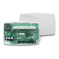
The 734N provides a Form C (SPDT) relay for controlling locks and other electronically-
controlled barriers. The three relay terminals marked NO C NC allow you to connect the device
wiring to the relay for module control.
When the 734N is powered with a 12/24 V power supply or POE, the device can power an
electric strike, up to 750 mA. See Figures 3 and 4 for typical magnetic lock and door strike
wiring. See Figure 5 for POE door strike wiring.
The Form C relay draws up to 35 mA of current and contacts are rated for 10 Amps (resistive)
at 12/24 VDC. When connecting multiple locks to the Form C relay, the total current for all locks
cannot exceed 10 Amps. If the total current for all locks exceeds 10 Amps, problems may arise
and an isolation relay may be needed. See Isolation Relay for more information.
NETWORK CONNECTION
Connect an IP network cable from the LAN/WAN connection to the 734N Network connector.
The 734N communicates AES encrypted TCP with panels that have network installed.
Two LED’s are located on the ethernet jack.
▸ The green LED indicates data sent to the panel.
▸ The yellow LED indicates the speed of the transmission. A solid yellow LED indicates
the network is connected at 100 Base-T. A flashing yellow LED indicates the network is
connected at 10 Base-T.
2
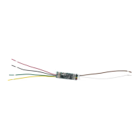
WIRE THE ELECTRONIC LOCK