Digital Monitoring Products XR150/XR550 Series Installation Guide
8
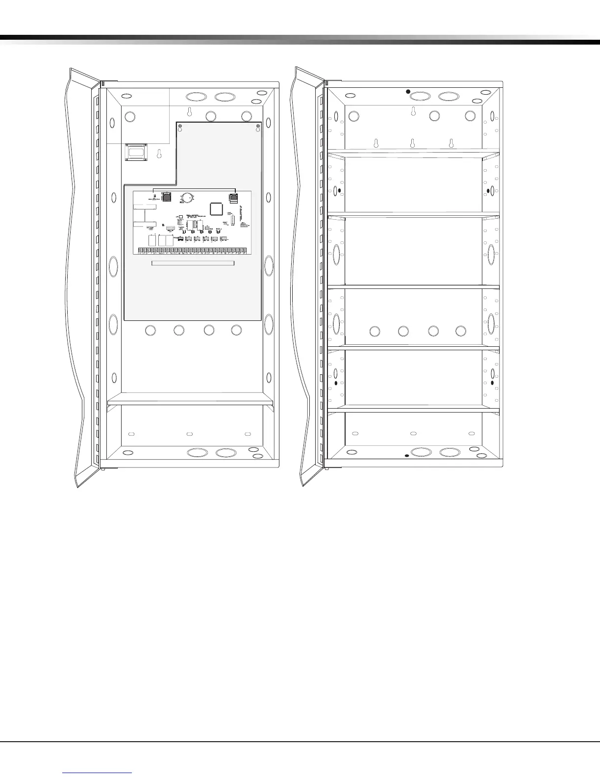
INSTALLATION
56 VA
Transformer
Mounting for one (1)
Zone Expansion Module.
Battery Shelf
Mounting
Plate
XR550 Panel
XR550 Panel
J6
K
Figure 4: XR550 Series in Model 352X Enclosure and Separate 352S Enclosure with Shelves
4.2 Mounting Keypads and Zone Expansion Modules
DMP LCD keypads have removable covers that allow you to easily mount the keypad to a wall or other at surface
using the screw holes on each corner of the base. All DMP keypad housings are designed to easily install on any 4”
square box, 3-gang switch box, DMP 695 and 696 backbox, or a at surface.
The keypad housing is made up of two parts: the front, which contains the circuit board and keyboard components
and the base. Use the following steps and gures to separate the keypad front and base.
1. Insert a at screwdriver into one of the slots on the bottom of the keypad and gently lift the screwdriver
handle toward you while pulling the halves apart. Repeat with the other slot.
2. Using your hands, gently separate the front from the base and set the front and components aside.
3. Before mounting the base, connect the keypad wire harness leads to the keypad cable from the panel and to
any device wiring run to that location. Then attach the harness to the pin connector on the PC board, mount
the base, and install the keypad cover making sure all of the keys extend through their respective holes.
The DMP 711, 712-8, 714, 715, 716, and 717 modules are each contained in molded plastic housings with removable
covers. The base provides you with mounting holes for installing the unit to a wall, switch plate, or other surface.