Digital Monitoring Products XR150/XR550 Series Installation Guide
16
INSTALLATION
Smoke and Glassbreak Detector Output
9.1 Terminals 11 and 12
Terminal 11 supplies positive 12 Vdc Regulated to power 4-wire smoke detectors and other powered devices. This output
can be turned off by the user for 5 seconds using the Sensor Reset User Menu option to allow latched devices to reset.
Terminal 12 is the ground reference for terminal 11.
9.2 Current Rating
The Output current from terminal 11 is shared with terminals 7, 25, 27, and LX500-LX900.
The total current draw of all devices powered from the panel must be included with terminal 11 calculations
and must not exceed the maximum output rating.
Protection Zones
10.1 Terminals 13–24
Zones 1 to 8 (terminals 13 to 24) on the XR150/XR550 Series panel are all grounded burglary zones. For programming
purposes, the zone numbers are 1 through 8. Listed below are terminal 13 to 24 connection functions.
Terminal Function Terminal Function
13 Zone 1 voltage sensing 19 Zone 5 voltage sensing
14 Ground for Zones 1 and 2 20 Ground for Zones 5 and 6
15 Zone 2 voltage sensing 21 Zone 6 voltage sensing
16 Zone 3 voltage sensing 22 Zone 7 voltage sensing
17 Ground for Zones 3 and 4 23 Ground for Zones 7 and 8
18 Zone 4 voltage sensing 24 Zone 8 voltage sensing
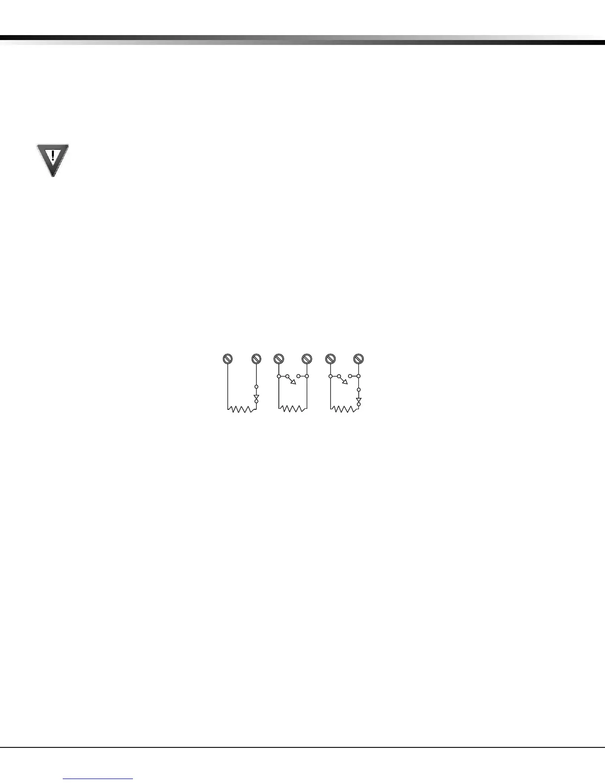
The voltage sensing terminal measures the voltage across a 1k Ohm End-of-Line resistor to ground. Use DMP Model 311 1k
Ohm resistors. Dry contact sensing devices can be used in series (normally-closed) or in parallel (normally-open) with any
of the burglary protection zones.
1K Ohm
Normally
Closed
1K Ohm
Normally Open
1K Ohm
Combination Normally Open
and Normally Closed
Figure 7: Protection Zone Wiring
10.2 Operational Parameters
Each protection zone detects three conditions: Open, Normal, and Short. Listed below are voltage and resistance
parameters for each condition:
Condition Resistance on zone Voltage on positive terminal
Open over 1300 ohms over 2.0 Vdc
Normal 600 to 1300 ohms 1.2 to 2.0 Vdc
Short under 600 ohms under 1.2 Vdc
10.3 Zone Response Time
A condition must be present on a zone for 500 milliseconds before it is detected by the XR150/XR550 Series panel. Ensure
detection devices used on the protec tion zones are rated for use with this delay. Zones 1-10 can also be programmed for a
fast response delay of 160 milliseconds.
10.4 Keyswitch Arming Zone
Using a keyswitch on an Arming type zone allows you to arm and disarm selected areas without having to enter a user code.