XR150/XR550 Series Installation Guide Digital Monitoring Products
23
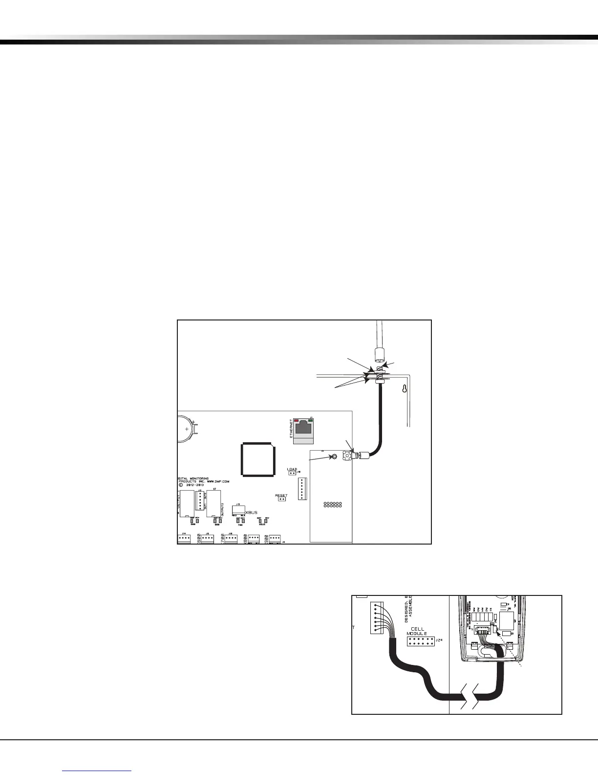
INSTALLATION
Cellular Modules
19.1 CELL MODULE Header
The CELL MODULE header is located to the right of the EXP Expansion Module on the right side of the circuit board
and is used to connect the DMP Model 263C CDMA or 263H HSPA+ Cellular Communicators. This provides a fully
supervised alarm communication path for the XR150/XR550 panel. Refer to the 263C (LT-1264), or 263H (LT-1270)
Installation Sheet for complete information.
19.2 Module Installation
1. Insert the PCB standoff end with anges into the standoff hole in the panel PCB.
2. Align the PCB standoff with the standoff hole in the module PCB.
3. Press the module PCB card 12 pin connector onto the CELL MODULE connector on the panel while applying
even pressure to both sides of the board to fully seat the module. See Figure 13.
Note: DO NOT MISALIGN THE CELL MODULE 12 PIN CONNECTOR ONTO THE CELL MODULE HEADER. If needed, the
PCB can be removed from the enclosure to allow placement of the cell module.
19.3 Connecting the Antenna
1. Attach a 381 cable to the SMA connector on the cell module.
2. Position one of the supplied washers onto the other end of the 381 SMA connector and push the threaded end
through an enclosure knockout.
3. Position the second washer onto the threaded end extending through the knockout and secure the nut.
4. Attach the included 383 Antenna to the SMA connector. See Figure 13.
Note: As an alternative, an antenna coax can be connected directly to the cell module SMA connector when the
coax enters the enclosure via conduit.
Wi-Fi Connection
20.1 763 Module to EXP Header
The 763 Wi-Fi Module allows you to add Wi-Fi alarm signal
communication to XR150/XR550 Series panels. The 763 connects
to the 7- pin EXP header on compatible panels using the included
cable and operates at 12 VDC from the panel power supply.
The 763 Wi-Fi Module is compatible with all DMP XR150 Series
Version 112 or higher rmware with Level F hardware and XR550
Series control panels Version 112 or higher rmware. Refer to
the 763 Wi-Fi Module Installation Guide (LT-1421) for complete
information.
Figure 13: Cellular Module Installation
XR150/XR550 Panel
SMA
Connector
PCB
Standoff
Celular Module
Nut
Washers
SMA
Connector
Antenna
Connector
Coax Cable from
Cellular Module
Model 381-2
Coax Cable from
the 263 module
J6
Included 3ft Cable
Link LED
J6
EXP
Figure 14: 763 to XR150/XR550 Series