Digital Monitoring Products XR150/XR550 Series Installation Guide
2
PANEL SPECIFICATIONS
1.7 Enclosure Specications
The XR150/XR550 Series panels are shipped in an enclosure with a transformer, End-of-Line resistors, battery leads,
user’s guide, and programming sheets.
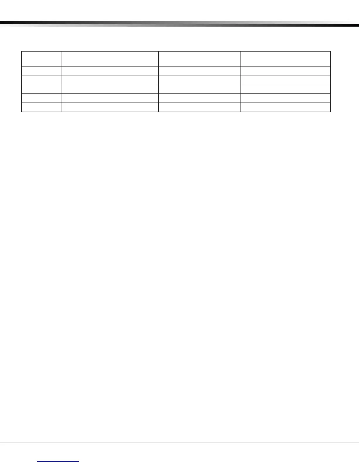
Enclosure
Model
Size Color(s) Construction (Cold Rolled
Steel)
350 17.5”W x 13.5”H x 3.5”D Gray (G) or Red (R) 18-Gauge
350A 17.5”W x 13.5”H x 3.75”D Gray (G) 18-Gauge with 16-Gauge door
341 13.22”W x 7.0”H x 3.5”D Gray (G) 20-Gauge
349 12.5”W x 11.5”H x 3.5”D Gray (G) 20-Gauge
352X 14.5”W x 32.0”H x 4.0”D Gray (G) 16-Gauge
Panel Features
2.1 Description
The DMP XR150/XR550 Series system is made up of an alarm panel with a built-in communicator, an enclosure,
battery, one transformer, and keypads. Each panel is a versatile 12 Vdc, combined access control, burglary, and
re communicator panel with battery backup. The panels provide eight on-board burglary zones and two on-board
12 Vdc Class B powered zones. The powered zones have a reset capability to provide for 2-wire smoke detectors,
relays, or other latching devices. Combined current requirements of additional modules may require an auxiliary
power supply. Refer to the Power Requirements section in this guide when calculating power requirements.
The panels can communicate to DMP SCS-1R Receivers using digital dialer, cellular, network, or Contact ID
communication. Panels using cellular, network, or encrypted communication can also communicate to DMP SCS-VR
Receivers.
2.2 Zone Expansion
Each panel provides multiple options for zone expansion:
• 10 on-board zones
• Up to 64 programmable keypad zones
• Up to 500 LX-Bus zones
Using DMP LCD keypad remote zone capability and zone expansion modules, additional zones are available on each
panel:
• XR550 provides up to 574 additional zones
• XR150 provides up to 142 additional zones
The panel keypad data bus supports up to 16 supervised device addresses with each address supporting up to four
programmable expansion zones (64 total).
Using the on board LX-Bus connections, and any combination of single, four, eight, or sixteen-zone expansion
modules and single-zone LX-Bus detectors, additional zones are available on each panel:
• XR550 provides up to 500 additional zones (LX500-LX900)
• XR150 provides up to 100 additional zones (LX500)
Note: Do not use shielded or twisted pair wiring for LX-Bus or Keypad Bus circuits.
2.3 Output Expansion
In addition to the two SPDT relays and four programmable open collector outputs on the XR150/XR550 Series, you
can also connect up to 25 programmable Model 716 Output Expansion Modules to each LX-Bus. These modules can
provide an additional 500 or 100 programmable SPDT relays.
The panels provide Output Schedules for programming the 716 to perform a variety of annunciation and control
functions. Also assign the 716 outputs to any panel Output Options such as Fire Alarm, Communication Fail, or Phone
Trouble Outputs. Refer to the 716 Installation Guide (LT-0183).
The LX-Bus also supports the Model 717 Graphic Annunciator Module. Each 717 module supplies 20 switched ground
outputs that follow the state of their assigned zones.
Note: The 717 supports the rst eight Keypad Bus addresses. To follow Keypad Bus addresses nine through 16, install
multiple 716 modules. Refer to the 717 Installation Guide (LT-0235) and 716 Installation Guide (LT-0183).