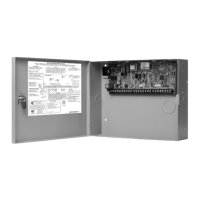
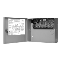
XR150/XR550 Series Installation Guide Digital Monitoring Products
17
INSTALLATION
Powered Zones for 2-Wire Smoke Detectors
11.1 Terminals 25–26 and 27–28
Panel terminals 25 through 28 provide two resettable Class B, Style A, 2-wire powered zones. For programming
purposes the zone numbers are 9 and 10.
Note: The maximum wire length for either zone 9 or zone 10 is 3000 feet using 18 AWG or 1000 feet using 22 AWG.
The maximum voltage is 13.8 Vdc and the maximum normal standby current is 1.25mA DC. The maximum line
impedance is 100 Ohms. The maximum short circuit current is 56mA. When using zone expansion modules, use Model
309 EOL resistors. The compatibility identier for the zones is A.
Note: Do not mix detectors from different manufacturers on the same zone.
Caution: Performing a Sensor Reset momentarily drops power to the devices on Zones 9 and 10. The panel
views these zones (9 and 10) as “Open” while the power is absent.
Note: Refer to the Compliance Listing Guide LT-1330 for list of Compliance 2-wire smoke detectors.
Dry Contact Relay Outputs
12.1 Description
The XR150/XR550 Series panel provides two programmable auxiliary SPDT relays when equipped with two DMP Model
305 relays in sockets OUTPUT 1 and OUTPUT 2 and a Model 431 Output Harness on the
OUT1-OUT2 6-pin Header. Each relay provides one SPDT set of contacts that can be operated by any of the functions
listed below:
1. Activation by zone condition: Steady, Pulsing, Momentary, and Follow
2. Activation by 24-hour 7-day schedule: One on and one off time a day for each relay
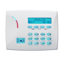
3. Manual activation from the DMP LCD keypad menu
4. Communication failure 12. Ready
5. Armed area annunciation 13. Armed
6. Fire Alarm, Fire Trouble or Supervisory 14. Disarmed
7. Ambush Alarm 15. Burglary
8. Exit and Entry timers 16. Phone Trouble
9. System Ready 17. Device Fail
10. Late to Close 18. Sensor Reset
11. Panic Alarm 19. Closing Wait
Refer to the XR150/XR550 Series Programming Guide (LT-1232) for specic information.
12.2 Contact Rating
The Model 305 relay contacts are rated for 1 Amp at 30 Vdc (allows .35 power factor). Connect auxiliary power
to the Relay Output 1 common terminal by installing the gray harness wire to terminal 7. Current draw for all
connected devices must not exceed the panel maximum current rating.
12.3 Model 431 Output Harness Wiring
The relay contacts are accessible by installing the DMP 431 Output Harness on the 6-pin OUT1-OUT2 header.
OUTPUT 2 uses the top three prongs, and OUTPUT 1 uses the bottom three prongs. The wire harness and contact
locations are shown below:
Contact Color
Output 1 normally closed Violet
Output 1 common Gray
Output 1 normally open Orange
Output 2 normally closed Violet with white stripe
Output 2 common White with gray stripe
Output 2 normally open Orange with white stripe
The relay contacts must be connected to devices located within the same room as the XR150/XR550 Series panel.
 Loading...
