XR150/XR550 Series Installation Guide Digital Monitoring Products
21
INSTALLATION
PHONE LINE RJ Connector
17.1 Description
Connect the panel to the public telephone network by installing a DMP 356 RJ Cable between the panel PHONE LINE
connector and the RJ31X or RJ38X phone block. The maximum impedance is 100 Ohms. CAUTION - To reduce the risk
of re, use only No. 26 AWG or larger telecommunication line cord, such as DMP Model 356 Series Phone Cords.
17.2 893A or 277 Connector
Connect an 893A Dual Phone Line Module or Model 277 Trouble Sounder to the 893A OR 277 connector on the panel.
Refer to the 893A Installation Sheet (LT-0135) or 277 Installation Sheet (LT-1304) for complete information.
17.3 Notication
The user must not repair registered terminal equipment. In case of trouble, immediately unplug the device from the
telephone jack. The factory warranty provides for repairs. Registered terminal equipment may not be used on party
lines or in connection with coin telephones. No tify the telephone company with the following information:
a. The particular line(s) where the service is connected
b. The FCC registration number as listed in Section 17.5
c. The ringer equivalence
d. The device make, model, and serial number
17.4 Phone Line Monitor
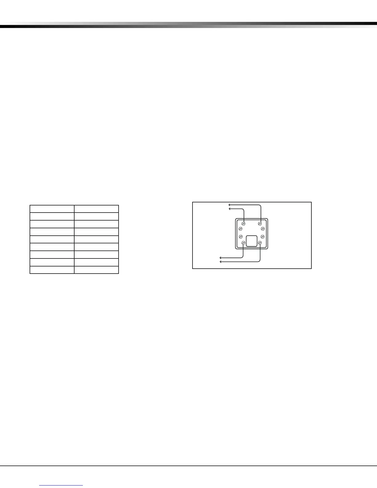
The XR150/XR550 Series panel has a built-in telephone monitor that monitors the phone line voltage to verify the
connection to the central ofce. Figure 11 and the table below identify the phone block pin layout, wire numbers,
and colors.
Wire Number Wire Color
1 Gray
2 Orange
3 Black
4 Red
5 Green
6 Yellow
7 Blue
8 Brown
The wires on the RJ31 that feed pins 4 and 5 should be the ONLY wires on the D-marc. All other house phone wiring
should be tied to pins 1 and 8 coming back from the RJ31.
Dial tone must come into RJ31X on pins 4 and 5 and go back to house phones from pins 1 and 8. Follow these steps
to determine if panel is seizing the line:
1. Unplug phone cord from RJ31X
2. Place butt-set on pins 4 and 5
3. Listen for dial tone. With dial tone present, lift either wire from pins 1 or 8
4. Listen for dial tone again. If the dial tone is present, RJ31X wiring is correct. If no dial tone is present, the
RJ31X wiring is backwards. Rewire so dial tone is coming IN on 4 and 5.
If you still have trouble with the phone line, you may need to replace the RJ cord. If the dial tone is still not
present, swap out the RJ31X phone block.
To Telephone
Line
RJ31X or RJ38X
Phone Block
8
7
6
54
3
2
1
Ring Tip
To Premise
Phone
Ring 1
Tip 1
Figure 11: Phone Jack Wiring