Digital Monitoring Products XR150/XR550 Series Installation Guide
20
INSTALLATION
15.3 LX-Bus/AX-Bus LEDs
The two LEDs, located above each LX-Bus/AX-Bus header, indicate data transmission and receipt. The left LED
ashes green to indicate the panel is transmitting LX-Bus/AX-Bus data. The right LED ashes yellow to indicate the
panel is receiving LX-Bus/AX-Bus data.
15.4 OVC LEDs
The Overcurrent LED (OVC) lights Red when the devices connected to the Keypad Bus and LX-Bus(es) draw more
current than the panel is rated for. The LED(s) turn a steady Red when lit. When the OVC LED(s) light Red, the
appropriate LX-Bus(es) and Keypad bus are shut down.
• The OVC LED located to the left of the 893A connector indicates overcurrent for the Keypad Bus (Terminals 7-10
and PROG header), XBUS, and LX500-LX700.
• The OVC LED to the right of the CELL MODULE connector indicates overcurrent for LX800-LX900.
ETHERNET Connector (Panels with Network/Encryption only)
16.1 Description
The ETHERNET Connector is available on the XR150/XR550 with network or encryption to connect directly to an
Ethernet network using a standard patch cable. The ETHERNET Connector supports 100MB/s full duplex operation
and the maximum impedance is 100 Ohms.
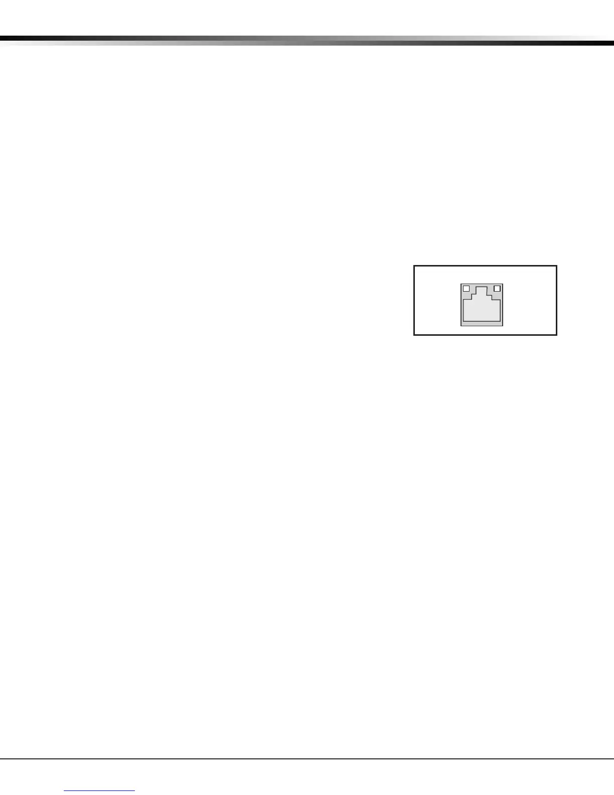
16.2 Ethernet LEDs
The two LEDs, located on the top edge of the ETHERNET Connector, indicate
network connection. The left, Link LED lights up yellow when connected to
a 100Mb network and is off when connected to a 10Mb network. The right,
Activity LED lights up green to indicate a valid receive connection from the
host network.
16.3 Network Transient Suppression
The Model 270 Transient Suppression Module provides surge suppression from
the Ethernet network for the protection of DMP Panels. Refer to the Model 270 Installation Sheet (LT-1316) for
complete information.
Figure 10: ETHERNET and LEDs
J1
Activity LED
Link LED