EasyManua.ls Logo

DMP Electronics XR150 series User Manual

DMP Electronics XR150 series
28 pages
To Next Page IconTo Next Page
Page #1 background imageLoading...
Page #1 background image
INSTALLATION GUIDE
XR150/XR550 SERIES
CONTROL PANEL
Question and Answer IconNeed help?

Do you have a question about the DMP Electronics XR150 series and is the answer not in the manual?

DMP Electronics XR150 series Specifications

General IconGeneral
BrandDMP Electronics
ModelXR150 series
CategoryControl Panel
LanguageEnglish

Summary

Product Specifications Summary

Power Supply Specifications

Details on the panel's power supply transformer and auxiliary power.

Communication Capabilities

Information on built-in network, encrypted, and Contact ID communication.

Panel Zone Configuration

Description of the panel's on-board burglary and powered zones.

System Components Overview

Important Caution Notes

Warnings and precautions for safe installation and operation.

System Wiring and Protection

Wiring Diagram Overview

Visual guide to connecting panel components and accessory devices.

Installation - Enclosure Mounting

Enclosure Mounting Locations

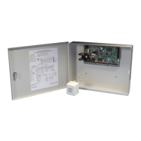
How to properly mount the XR150/XR550 enclosure.

Installation - Keypads and Expansion Modules

Installation - Bus Connections and Wireless Keypads

Connecting LX-Bus, AX-Bus, and Keypad Bus Devices

Guidelines for connecting devices to panel bus headers.

Installation - Power Supply Configuration

AC Terminals and Wire Gauge

Connecting AC transformer wires to panel terminals 1 and 2.

Transformer Type Selection

Guidance on selecting appropriate transformer types.

50VA-75VA Transformer Header

Using the 3-pin header for transformer current selection.

Battery Terminals Connection

Connecting batteries to terminals 3 and 4 for secondary power.

Installation - Power Requirements Calculation

Calculating System Power Needs

Determining total current draw for panel and accessories.

Installation - Battery Selection

Selecting Batteries for Standby Hours

Choosing batteries based on calculated Amp Hour requirements.

Installation - Protection Zones

Protection Zone Terminals

Details of terminals 13-24 for protection zone wiring.

Zone Operational Parameters

Voltage and resistance parameters for zone conditions.

Installation - Special Zone and Output Types

2-Wire Smoke Detector Powered Zones

Using terminals 25-28 for 2-wire smoke detector zones.

Installation - LX-Bus and AX-Bus Expansion

LX-Bus and AX-Bus Header Configuration

Connecting expansion modules to panel bus headers.

Installation - Network and Bus Status

Ethernet Connector Description

Connecting the panel to an Ethernet network.

Installation - Telephone Line Connection

Phone Line Connector Description

Connecting the panel to the public telephone network.

Installation - FCC and Reset/Tamper Headers

Reset Header Functionality

Using the reset header to reset the panel microprocessor.

Tamper Header for Enclosure Security

Connecting tamper switches to monitor enclosure opening.

Installation - Cellular and Wi-Fi Connectivity

Cellular Module Header and Installation

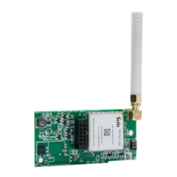
Connecting and installing the cellular communication module.

Wi-Fi Module Connection to EXP Header

Connecting the 763 Wi-Fi module to the panel's EXP header.

Installation - Wi-Fi Mounting, Certifications, and Export

Connecting the Wi-Fi Module (763)

Final connection steps for the 763 Wi-Fi module.

Related product manuals