EasyManua.ls Logo

Dometic SmartStart III - User Manual

Dometic SmartStart III
36 pages
Print Icon
To Next Page IconTo Next Page
Loading...
BasicChillerControl
OperationsManual
DometicGroupMarineDivision
Rev.20180709
L3527English
P/N338238
COPYRIGHT©20112018Dom et icGroupMarineDivision.AllRightsRes erved.
Nopartofthispublicationmaybere produced,t ranslated,storedinaretrievalsystem,ortransmittedinanyformorbyanymeanselectronic,
mechanical,phot ocopying,recordingorotherwisewithoutpriorwrittenconsentbyDometicMarine.Everyprecautionhasbeentakeninthe
preparationofthismanualtoinsureitsaccuracy.
However,DometicMarineassumesnoresponsibilityforerrorsandomission.Neitherisany
liabilit yassumedfordamagesresultingfromtheuseofthisproductandinf ormationcontainedherein.
Question and Answer IconNeed help?

Do you have a question about the Dometic SmartStart III and is the answer not in the manual?

Overview

The Dometic Basic Chiller Control Operations Manual describes a microcontroller-based unit designed to manage multiple chillers, offering flexibility in application and enhanced control and protection. This PLC Chiller system utilizes temperature differential and hysteresis for capacity management in single or multistage configurations.

Function Description:

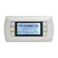
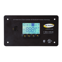
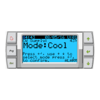
The Dometic PLC controls are designed to operate up to six chillers, one chilled water pump, one sea water pump, and up to six electric heaters. It sequences devices for runtime equalization, incorporates alarms and interlocks, and provides troubleshooting assistance. The primary interface is an LCD display, referred to as the PGD1 display. The system supports Cool, Heat, or Electric Heat mode operation in single-stage or multistage configurations.

Important Technical Specifications:

  • Temperature Sensors: NTC type 10K@77° thermistors are used for temperature measurements.
  • Pressure Transducers: Ratiometric 0-650 PSI (45 bar) range transducers monitor both suction and discharge pressures.
  • Relay Outputs:
    • COMP (Compressor): Provides switched power to the contactor coil for normal compressor operation.
    • CWP (Chilled Water Pump): Provides switched power to the contactor coils for the chilled water pump.
    • SWP (Sea Water Pump): Provides switched power to the contactor coils for the sea water pump.
    • RV (Reversing Valve): Provides switched power to the coils for the reversing valve.
    • EH (Electric Heat): Provides switched power to the contactor coils for the electric heat.
    • FAULT: Provides a Normally Open (NO) contact point that closes on any fault condition, outputting 230 VAC. This can be used for a light, relay, or interface to a ship's monitoring system.
  • Digital Inputs: Monitor the status of protection circuits, including:
    • FS (Chilled Water Flow Switch): Ensures flow before enabling the system or a stage. A loss of flow for more than 10 consecutive seconds disables the compressor or heat relay and records a fault.
    • Refrigerant HI (High Side Pressure Limit): De-energizes the compressor if the HI pressure switch is tripped, displaying a high-pressure fault.
    • Refrigerant LOW (Low Side Pressure Limit - Optional): De-energizes the compressor if the low-pressure switch is tripped, displaying a low-pressure fault.
  • Analog Inputs:
    • High Limit Temperature Setpoint: Continuously monitored. If supply water temperature exceeds 125°F (51.7°C), all enabled compressor/heater relays are de-energized. Re-energizes at 110°F (43.3°C).
    • Freeze Temperature Setpoint: Continuously monitored. If supply water temperature drops to 38°F (3.3°C) or below, the compressor relay is de-energized. Re-energizes at 42°F (5.6°C).
    • Condenser Freeze Protection (Optional): A sensor on the condenser coil monitors temperature. In heat mode, if coil temperature drops below 40°F, compressor speed is halved, and "Freeze Defrost" is displayed.
  • Modbus Connection: A 3-wire Modbus connection is included for multistage configuration and networking with a boat management system.
  • Power Supply: The control power supply operates at 240V/1Ø.

Usage Features:

  • PGD1 Navigation:
    • Enter Button: Enables/disables the chiller from the Main screen, navigates to editable screen areas, and scrolls down to selections.
    • Scroll Up/Down Buttons: Modify values (e.g., temperature setpoints, probe adjustments) and navigate between pages. The flashing cursor must be in the upper left corner for page navigation.
    • Esc Button: Exits the current screen, returning to the previous one, and eventually to the Main screen.
    • Prg Button: Accesses system menus. Scroll buttons navigate options, and Enter selects an item.
  • Operational Modes:
    • Cooling Mode: Activated by selecting "Cool." Compressor relay energizes if return/supply water temperature is above the cooling setpoint and staging delay has elapsed. Minimum run time is 100 seconds, minimum off time is 120 seconds.
    • Heating Mode (Reverse Cycle): Activated by selecting "Heat." Reversing valve energizes. Compressor relay energizes if return/supply water temperature is below the heating setpoint and staging delay has elapsed.
    • Heating Mode (Electric Heat - Optional): Activated by selecting "Electric Heat." Heater relay energizes if return/supply water temperature is below the heating setpoint and staging delay has elapsed.
  • Pump Operation:
    • Chilled Water Pump (CWP): Relay closes 5 seconds before the first stage is enabled, running continuously when the system is enabled.
    • Sea Water Pump (SWP): Selectable operating mode (continuous or cycle with compressor demand). Default is to cycle with demand, closing 5 seconds before compressor start and opening 5 seconds after the last compressor cycle. Disabled if immersion heating is used.
  • Compressor Staging: Compressor rotation ensures runtime equalization. The compressor with the lowest running hours is enabled first. Staging time is adjustable from 10 to 110 seconds in 10-second increments.
  • Setpoints:
    • Cooling Setpoint: Adjustable from 48°F (8°C) to 58°F (14°C) for return control, and 42°F (5°C) to 58°F (14°C) for supply control.
    • Heating Setpoint: Adjustable from 95°F (35°C) to 120°F (49°C) for both return and supply control.
  • Status Screen Navigation: The main home screen displays single-stage operation or allows scrolling through parameters for additional stages. It indicates the mode of operation (Cool, Heat, EH) and any active alarms.
  • Networking: Stages must be configured individually before connecting them to the network. Each display and I/O board in a multistage system requires a unique address.
  • Time and Date Setting: Allows users to set the current date and time, with daylight saving enabled by default.

Maintenance Features:

  • Alarm Button: Flashes red for active alarms. Pressing it displays the active alarm screen, showing system parameters at the time of the fault. Holding for 3 seconds clears the alarm once the fault is corrected.
  • Alarm History (Menu E): Captures the status of parameters at the time of an alarm. The most recent alarm is shown, with the ability to view previous alarms.
  • Service Menu (Menu G): Requires a password (contact Dometic). Includes submenus for:
    • Information: Displays service contact, firmware, flash RAM, power cycle status, and Evo firmware information.
    • Commission: Allows technicians to enter dealer contact information and commission the system.
    • Working Hours: Displays actual compressor run hours and number of starts.
    • BMS Config: Used for configuration with STIIC network.
    • Test Mode: Disabled by default.
    • Service Settings:
      • Working Hour Set: Sets service intervals and allows resetting or setting run hours if a compressor or board has been replaced.
      • Probe Adjustment: Selects sensor curves (10k or 30k) and calibrates installed temperature/pressure sensors.
      • Thermoregulation: Sets superheat setpoints (Cool, Heat, Setpoint SH, LowSH thresh, LOP thresh, MOP thresh).
    • User Save: Saves or restores user-specific settings and enables auto-save.
    • Stage Address: Changes unit addresses in multistage configurations to avoid conflicts.
    • Stage Disable: Allows technicians to take a stage offline for repairs while the rest of the system remains operational.
    • Manual Management: Manually operates relay outputs and enables/disables analog sensors.
  • Firmware Compatibility Check: Users are advised to ensure that the firmware versions of all chillers match to prevent networking problems. Re-flashing by a Dometic approved engineer may be required if versions differ.

Dometic SmartStart III Specifications

General IconGeneral
BrandDometic
ModelSmartStart III
CategoryController
LanguageEnglish

Related product manuals