4
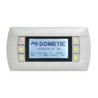
AlarmButton
Thisbuttonwillflashredifthereisanactivealarm.Pressingthisbuttonwilltakeyoutotheactivealarmscreentodisplaythealarm.
Onceinthealarmscreen,usetheup/downbuttonstoscrollthroughalarms.TheAlarmscreencapturesasnapshotofthesystem
parametersatthe
timeofthefault.PressandholdtheAlarmbuttonfor3secondstocleartheactivealarmifthefaulthasbeen
corrected.
GE
NE
RALINFORMATION
TheDometicPLCcontrolsisamicrocontroller‐basedunitdesignedtocontrolmultiplechillers.Thisdesignallowstheuserflexibility
intheapplicationandimprovedcontrolsandprotection.ThePLCChillerusestemperaturedifferentialandhysteresistomanage
thecapacityofthechillerinsingleormultistageapplication.
Thechillersystemwillcomeprogrammedfromthefactorywiththeoptionsenabledforthatsystem.Althoughthesystemoffers
flexibility,theseoptionscanonlybeenabledbyafactoryrepresen tative.
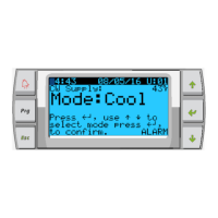
TheuserwillbeabletoselectbetweenCool,HeatorElectricHeatmodeoperationinsinglestageconfigurationorIna
multistage
configuration.
ThePLCcontrollerisinte rnallygroundedwithisolationbetweeninputsandoutputs.Additionally,theoutputrelaysofferdouble
isolationsothatdifferentvoltagescanbeusedforgroupsofrelays.
Thesystemwillutilizevarioussensortypesformeasuringanalogtemperaturesandpressures.Fortemperaturemeasurements,the
systemwilluseNTCtype10K@77°thermistors.Pressuretransducersareratiometric0‐650PSI(45bar)rangeforbothsuctionand
dischargemonitoring.
AvailableOptions:
1. CompressorCurrentMonitoring
2. PumpCurrentMonitoring(SWandCW)
3. CondenserFreezeProtection
4. ElectricHeat
5. EEVControl
6. PressureTransducers
7. LoadSheddingInputSignal
8. LowCurrentAlarmtoindicateifsystemisnotactuallyrunningwhenenabled.(PumpsandCompressor)
9. Return
orSupplyWaterControl
DIGITAL
IN
PUTS
Digitalinputsareusedtomonitorthestatusoftheprotectioncircuitsforthesystem.
SAFETY I
NP
U
T
S
Alldiscreteinputswillbecheckedbeforethesystemwillbeenabled.Anyfaultsdetectedonstart‐upmustbeverifiedandcleared
viathePLCbeforesystemwillstartnormaloperation.
FS–
CHILLED WATER FLOW
SWIT
C
H
WiththesystemineitherheatingorcoolingmodetheFlowswitchmustbeclosedpriortosystemstartingorastagebeingenabled.
InoperationifFlowislostformorethan10consecutiveseconds,thecompressororheatrelaywillbedisabled.Aflowswitchfault
willbe
recordedanddisplayed.
ACWFlowfaultwillberecordedandsystemwillbeinlockoutandamanualrestartwillberequired.ThePLCwillnotallowthecompressor
orelectricheatrelaytobeenergizedforthestagethathaslostfloworthewholesystemifacommonflowswitchisbeingused.
FaultmustbemanuallyacknowledgedviathePLCandclearedpriortore‐enablingthesystemorstage.
REFRIGERANT
HI–
HIGH SIDE PRESSURE
L
IM
I
T
ThePLCwillimmediatelyacknowledgeanopencircuitiftheHIpressureswitchistrippedandde‐energizethecompressor.Itwillrecord
anddisplayhighpressurefaultonthealarmscreen.IfthePLCdetectsahighpressurefaultduringoperation,aHPfaultwi llbedisplayed
andrecorded.
ThePLCwillnotallowthecompressorrelaytobere‐energized,un tilswitchisintheclosedposition.
ThefaultmustbemanuallyacknowledgedviathePLCandclearedpriortore ‐enablingthesystemorstage.