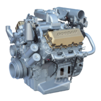
DV11
Operation and Maintenance
142
Common Rail Fuel-injection System
Printed in Mar. 2005 PS-MMA0608-E1A
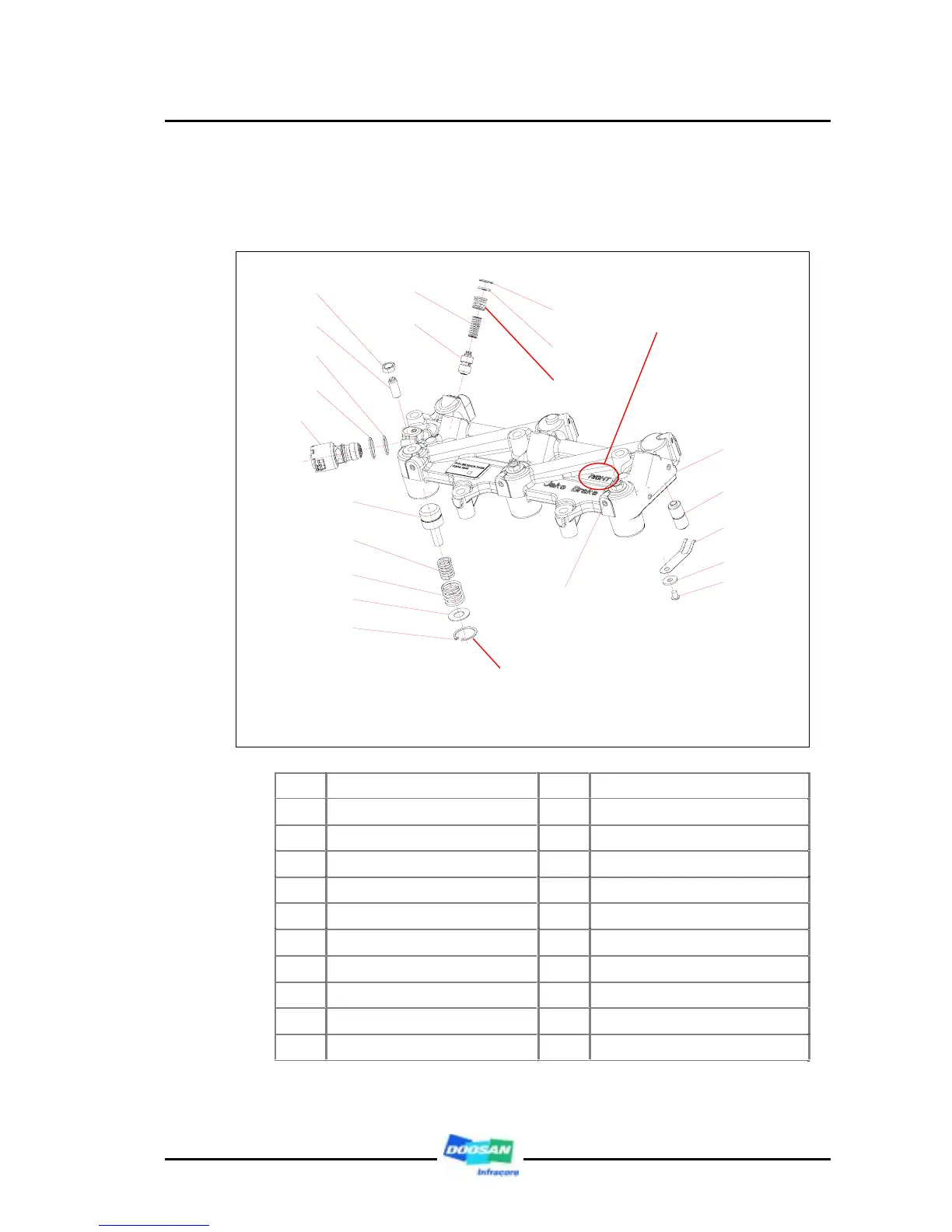
3.6. Engine brake
3.6.1. Engine brake construction
1 Adjusting nut 12 Spring (inner)
2 Adjusting screw 13 Spring (outer)
3 Sealing (center) 14 Spring retainer
4 Sealing (upper) 15 Stopping ring
5 Solenoid valve ass’y (24V) 16 Plug screw
6 Spring (inner) 17 Housing (for right)
7 Control valve ass’y 18 Master piston
8 Snap ring 19 Plate spring
9 Control valve cover 20 Washer
10 Spring (outer) 21 Screw
11 Slave piston
1
2
3
4
6
7
8
9
11
13
14
15
16
21
18
19
20
5
17
12
10
CAUTION:
Assemble the snap ring opening portion of it in
positioned to the opposite side of the opening
surface of the housing. (180°)
RIGHT mark:
Be assembled to the
left side at the view of
crank shaft pulley