ED700
Low Energy
Automatic Swing Door
DORMA
10
DORMA AUTOMATICS, Inc. 924 Sherwood Drive Toll-Free: 877-367-6211
Lake Bluff, IL 60044 Fax: 877-423-7999
DL3038-010 Rev. B 6/08
E-mail: automatics@dorma-usa.com Subject to change without notice
THI
AD
BY
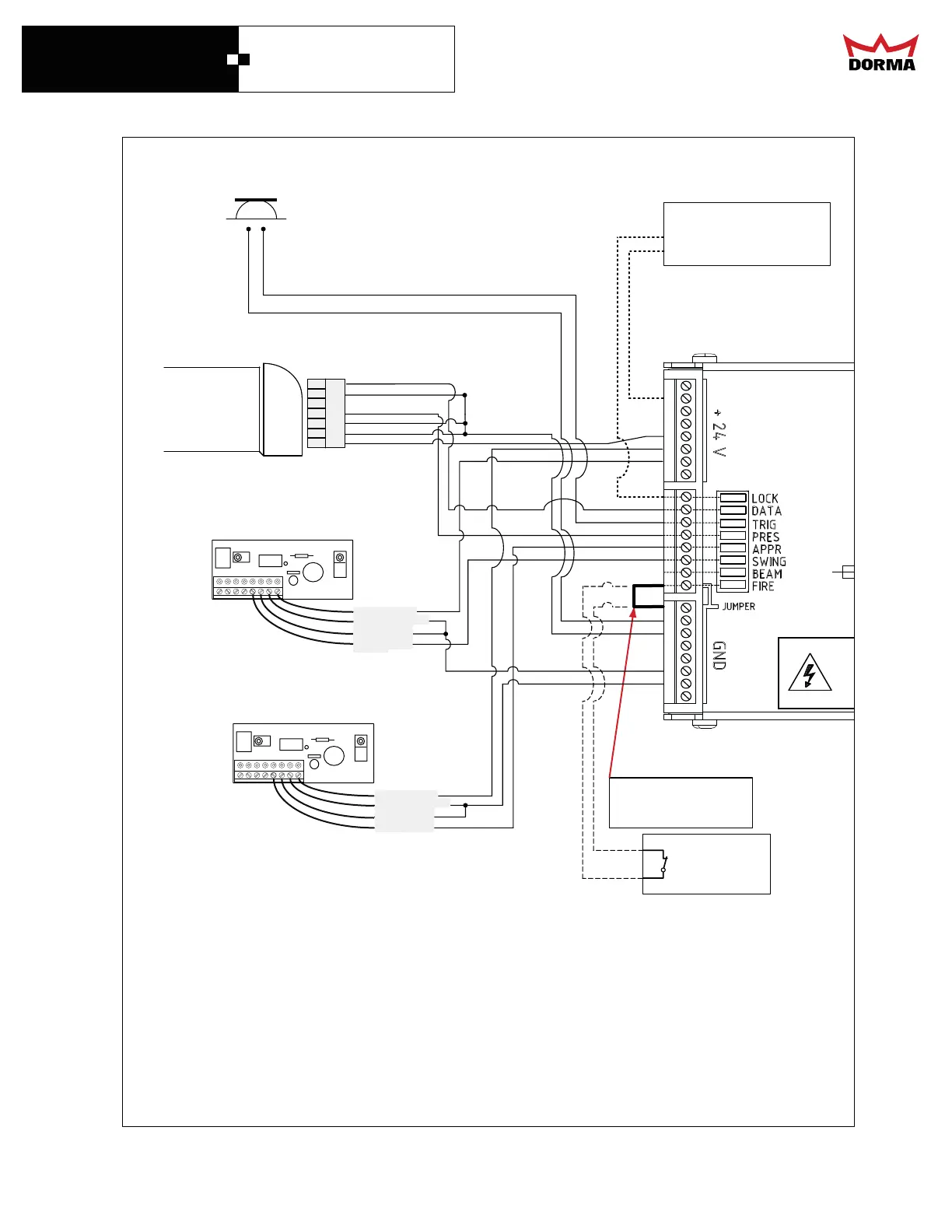
(Optional)Swing Side Door Mounted Sensor
MOUNTED TO SWING SIDE OF DOOR
MOUNTED TO APPROACH OF DOOR
GREEN (N.O.)
BLACK (-24 VDC)
RED (+24VDC)
WHITE (COM)
SMOKE
DETECTOR
(Optional)
PUSH BUTTON OR
ANY OTHER KNOWING
ACT ACTIVATION DEVICE
GREEN (N.O.)
BLACK (-24 VDC)
RED (+24VDC)
WHITE (COM)
Please see Sensors Manufacturer’s Installation Guides
for further instructions and wiring details.
Follow the installation and adjustment instructions accompanying the sensors
to be installed. Insure compliance with BHMA/ANSI Standards.
Jumper MUST be installed
if an optional smoke
detector is not present.
extra
extra
extra
(Optional)Approach Side Door Mounted Sensor
WIRING DIAGRAM FOR PUSH PLATES AND OPTIONAL ACCESSORIES
MI
Isolation Relay
for electric locks
see page 22.
MOUNTED TO THE HEADER
Data+
Data-
NC
NO
COM
24V
24V
(Optional)
OVERHEAD
SWING AREA
PRESENCE
SENSOR
Do not connect electric strike
or magnetic lock directly to
the control