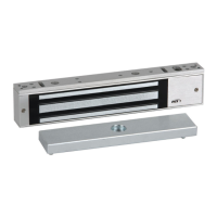
dormakaba Header Installation Instructions with EML310/320 and 371/372
For use with DRS Rails and Patching Fittings (4-1/8”, 4-1/2”, 6” Headers)
933903 07-2019EML Header Shim
14
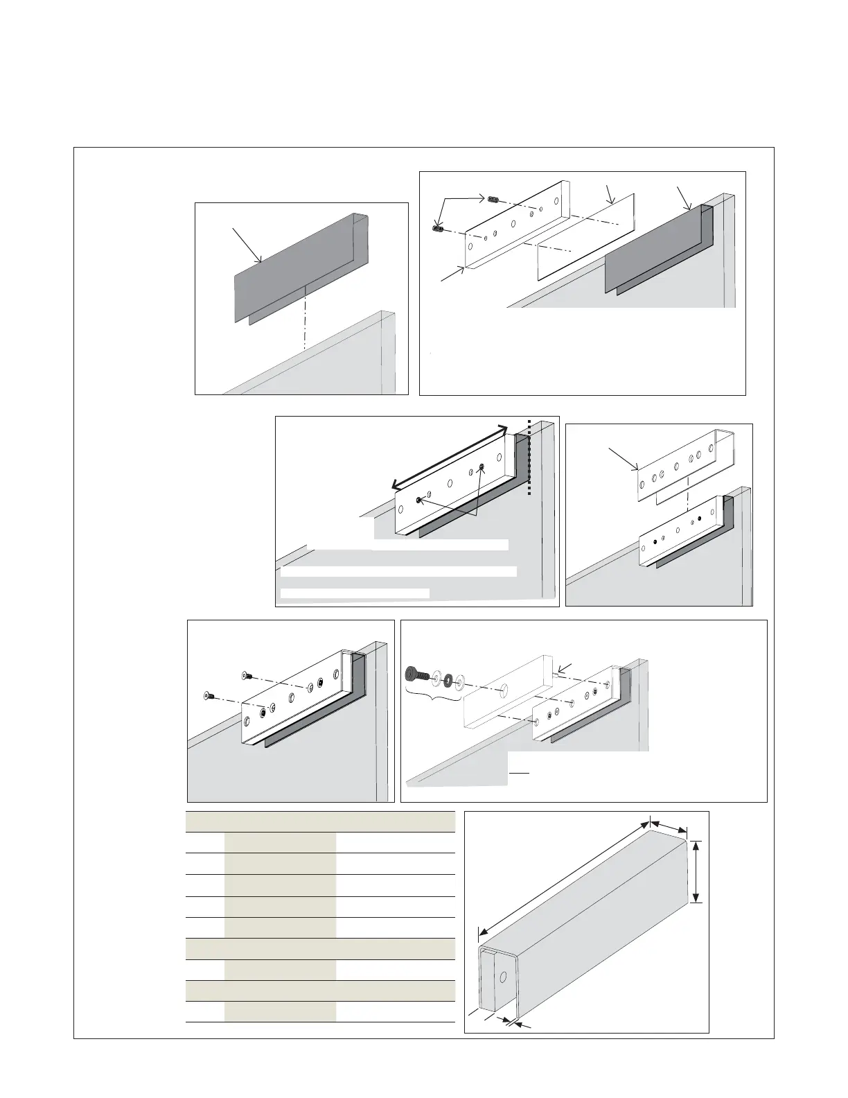
Install armature plate: patch fittings
4 Install armature plate
Fig.
4.1 (For use with patch fittings only) secure glass door bracket (GDB)
Dimensions
EML/ EML/
A .” [] .” []
B .” [.] .” [.]
C .” [.] .” [.]
D .” [.] .” [.]
1/2” model
E .” [] .” []
3/4” model
F .” [.] .” [.]
.. Temporarily and gently secure (hand-tighten) the
following glass door bracket parts to the glass panel:
• Black rubber shim
• Metal shim
• Armature securing plate
.. Gently secure with included set screws.
Black rubber
shim
Metal shim
Armature
securing plate
Set
screws
Black rubber
shim
.. Slide U-shaped bracket cover
over top of assembly.
.. Fully secure with included
fasteners.
.. Align armature plate via the pins.
.. Secure armature plate to bracket with the following included
center-mounting
bolt fasteners:
• Bolt with affixed
rubber washer
• Steel washer
• Rubber washer
• Steel washer
Mark
bracket
location
Glass door bracket assem
Set
screws
U-shaped
bracket
cover
Center-
mounting
bolt
Pin
Armature
plate
A
B
C
D
E
NOTE: Armature plate should remain movable. See
step 4.1.9 on this page.
NOTE: Armature
plate must be
allowed to pivot
on the center-
mounting bolt to
allow proper
alignment with
the magnet
surface. If not
properly aligned
with the magnet
surface, the lock
may lose holding
force or not lock at all.
NOTE: The head of the
armature mounting bolt ships
with a rubber washer affixed
to it. Ensure this washer
projects slightly beyond the
surface of to armature plate.
This is to allow the washer to
expand when power is removed
and break the air vacuum
between the
plate and the
magnet
surface. DO
NOT REMOVE
OR TRIM THE
WASHER. This
will cause the
lock to
continually have
some holding
force even when
power is
removed.
NOTE: Apply thread locking compound to exposed thread.
NOTE: TIGHTEN CENTER-MOUNTING BOLT
BUT, ALLOW FOR ARMATURE PLATE
MOVEMENT AND ALIGNMENT.
NOTE: Allow left-to-right movement of
glass door bracket assembly so it can
be properly aligned with mag
lock.
.. Close door to
align mag lock
and glass
door bracket
assembly.
Adjust bracket left or right if necessary.
.. Mark glass door bracket location on door.
.. Fully tighten set screws.