dormakaba Header Installation Instructions with EML310/320 and 371/372
For use with DRS Rails and Patching Fittings (4-1/8”, 4-1/2”, 6” Headers)
933903
07-2019EML Header Shim
19
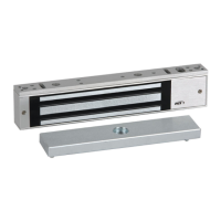
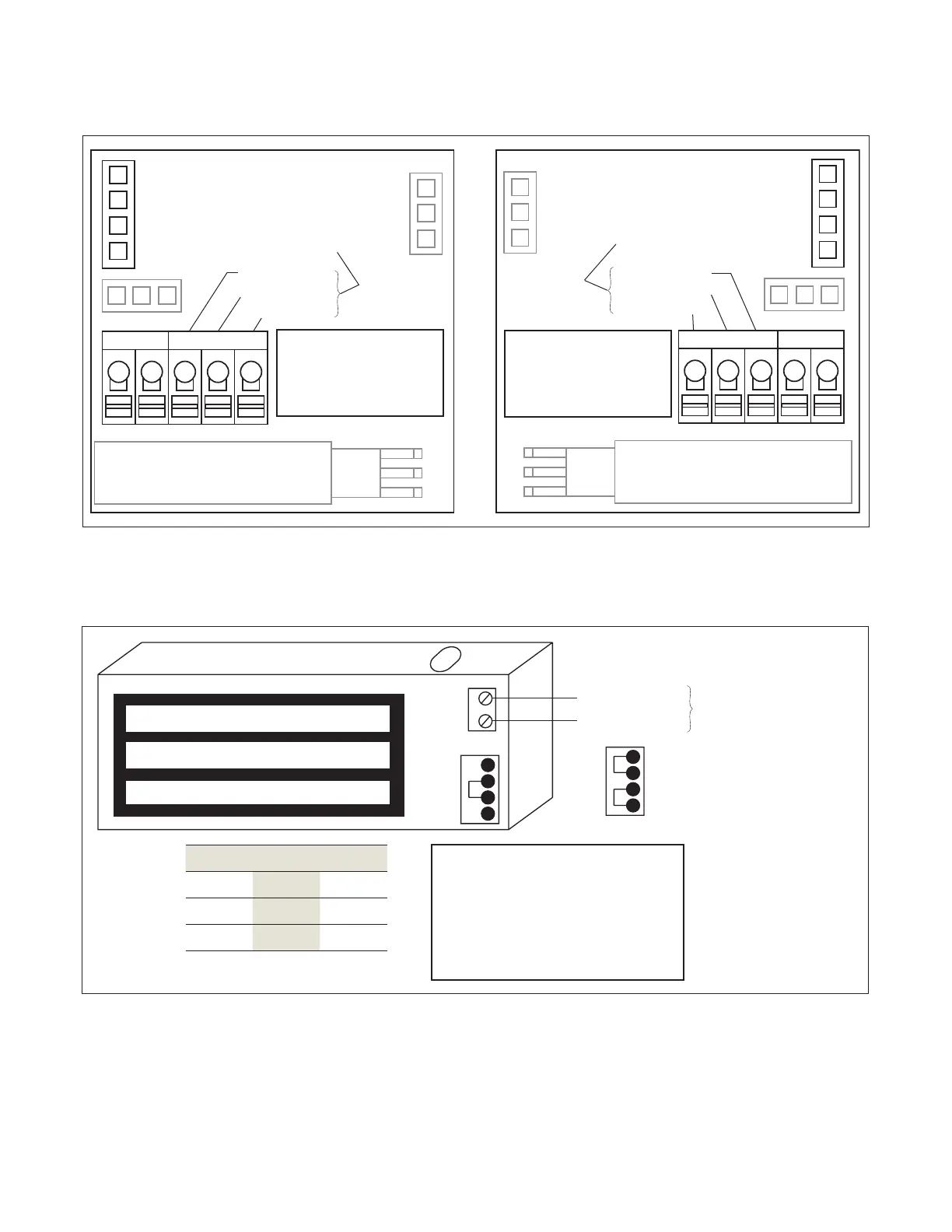
Wiring EML
Fig.
12 24 12
12 24 12
Voltage Jumpers
HR
R B G
VDC C NC NO
-
Tip: Fully depress orange tab to insert wires.
Common
Normally Closed
Normally Open
Optional BA Sensor SPDT
Output contacts rated for
maximum . Amperes at
VDC.
LED
G B R
LED
G B R
EML BA and EML BA
Side
EML BA
Side
Voltage Jumpers
LED
G B R
RB
G
HR
-
VDCCNONC
Tip: Fully depress orange tab to insert wires.
RG B
LED
Optional BA Sensor SPDT
Output contacts rated for
maximum . Amperes at
VDC.
Common
Normally Open
Normally Closed
Fig.
Power input requirements
Model 12VDC 24VDC
EML .A .A
EML .A .A
+/VDC input
- (Ground)
Magnet power from
Power Supply
Jumper VDC
Jumper
VDC
(preset)
Optional DP contacts are rated
.A @ VDC and .A at
VDC
2 x BLUE LEADS Normally Open
shown with Door Open
Optional DP contacts rated at
.A@VDC and .A@VDC
2 x BLUE LEADS Normally Open
Both the BA and DP options are
shown with Door Open
Optional DP contacts rated at
.A@VDC and .A@VDC
2 x BLUE LEADS Normally Open
Both the BA and DP options are
shown with Door Open
. Wiring for BA or BA DP combination models (for EML/)
. Wiring for Unmonitored or DP sensor models (for EML/)