dormakaba Header Installation Instructions with EML310/320 and 371/372
For use with DRS Rails and Patching Fittings (4-1/8”, 4-1/2”, 6” Headers)
933903
07-2019EML Header Shim
17
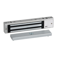
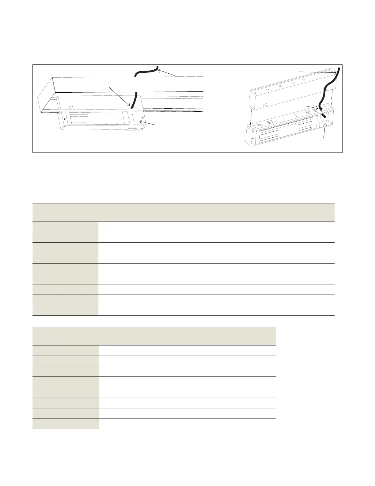
Wiring EML
Fig.
.. Remove wiring cavity cover.
.. Route the power supply connecting wire
through the frame/header tube/shim (as
necessary) and into the wire access hole.
Total one way
length of wire run (ft.)
Load current
1/4A 1/2A 3/4A 1A 1-1/4A 1-1/2A 2A 3A
--
--
-- --
-- -- --
-- -- -- --
-- -- -- -- --
-- -- -- -- -- -- --
-- -- -- -- -- -- --
NOTE: Power supply should be of sufficient gauge for
the lock being installed and the distance being run. See
Table 1 and 2 for reference.
Table Wire gauge selections - load current at V
Total one way
length of wire run (ft.)
Load current
1/4A 1/2A 3/4A 1A 1-1/4A 1-1/2A
--
-- --
-- -- --
-- -- -- --
-- -- -- --
-- -- -- -- --
-- -- -- -- --
Table Wire gauge selections - load current at V
Header
tube
NOTE: Header tube
hidden for easier
viewing.
Shim
Shim
Mag lock
body
Mag lock
body
Wiring
cavity
cover
Power
supply
NOTE: Shim
and lock body
exploded for
easier
viewing.
Wiring
cavity
Wire access
hole
Power
supply
These recommended wire gauge selection tables are based on the National Electrical Code ( NEC),
assume °F (°C) rated wire, include a % safety factor, and define the amperage ratings at the listed
distances that result in % voltage drop due to wire resistance. Five percent is normally acceptable in low voltage
systems.
6 Wiring the EML
. Wiring mag lock body through header (for EML/ and /)
Wire access
hole