CAN BUS system (only for EPS CAN)
5 CAN BUS system (only for EPS CAN)
1. CAN BUS components
max.
number/system
FST/Standard
Article numberArticles
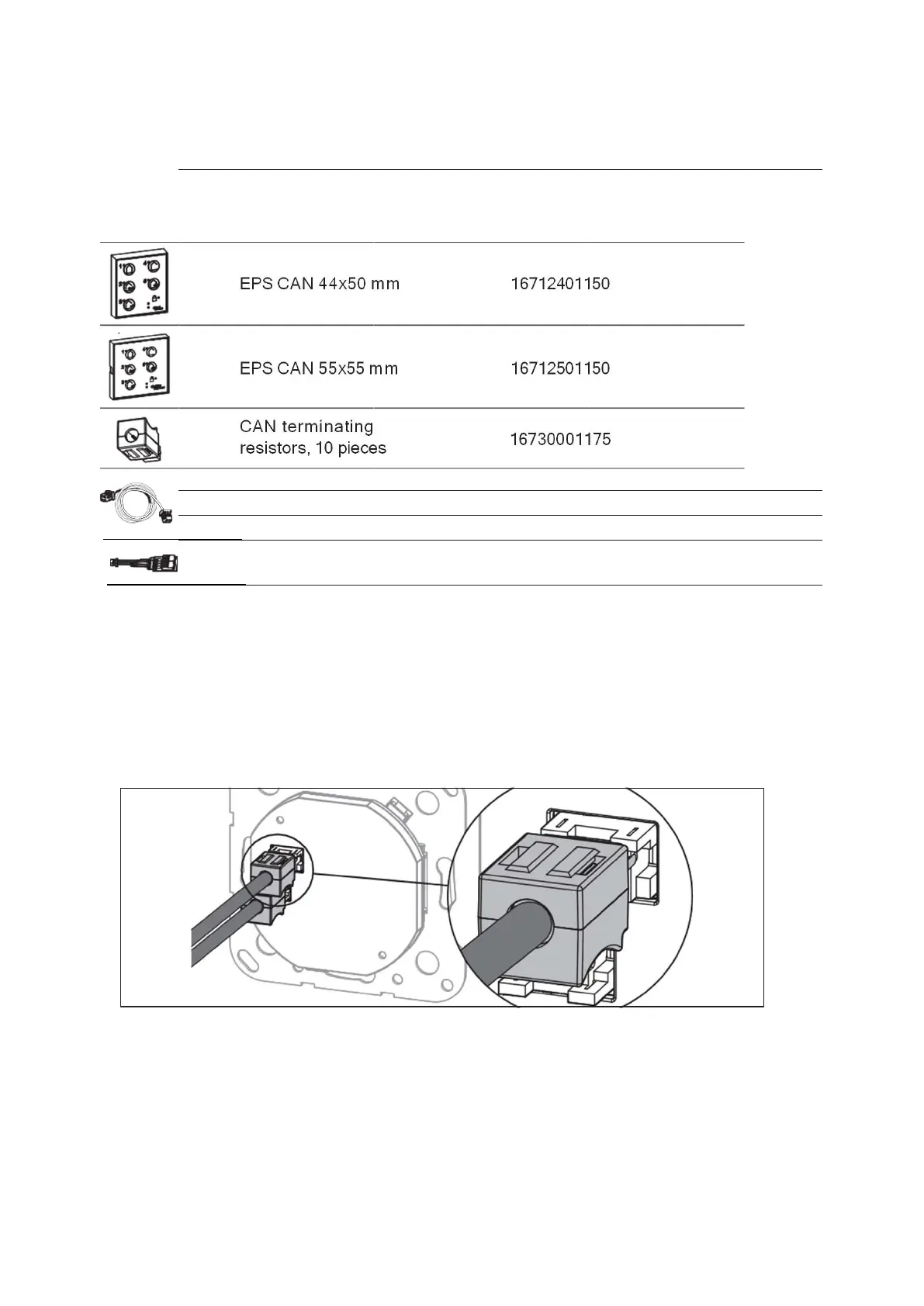
2/216712401150EPS CAN 44x50 mm
2/216712501150EPS CAN 55x55 mm
16730001175
CAN terminating
resistors, 10 pieces
16723101175CAN BUS cable, 3.4 m
16723301175CAN BUS cable, 6 m
16730601175CAN BUS extension, 3 m
16723801175
CAN BUS adapter, 2
pieces
5.2 Properties of CAN BUS systems
• The CAN BUS is a 4-wire bus, comprising + 27 V, GND and 2 data cables (CAN-L
and CAN-H).
• Because the connectors on the CAN BUS cables are very small, a housing is
sometimes mounted on the connectors. The housing makes it easier to connect
the connectors in hard-to-reach places. The curved side of the connecter is
always at the bottom.
Fig. 77
• The CAN BUS components are automatically detected by the control unit.
• If a CAN BUS component is replaced or removed from the network, a CAN BUS
reset must be carried out.
ES 250 PRO Easy
2024-03
46
ES250ProEasy Installation Manual



 To Next Page