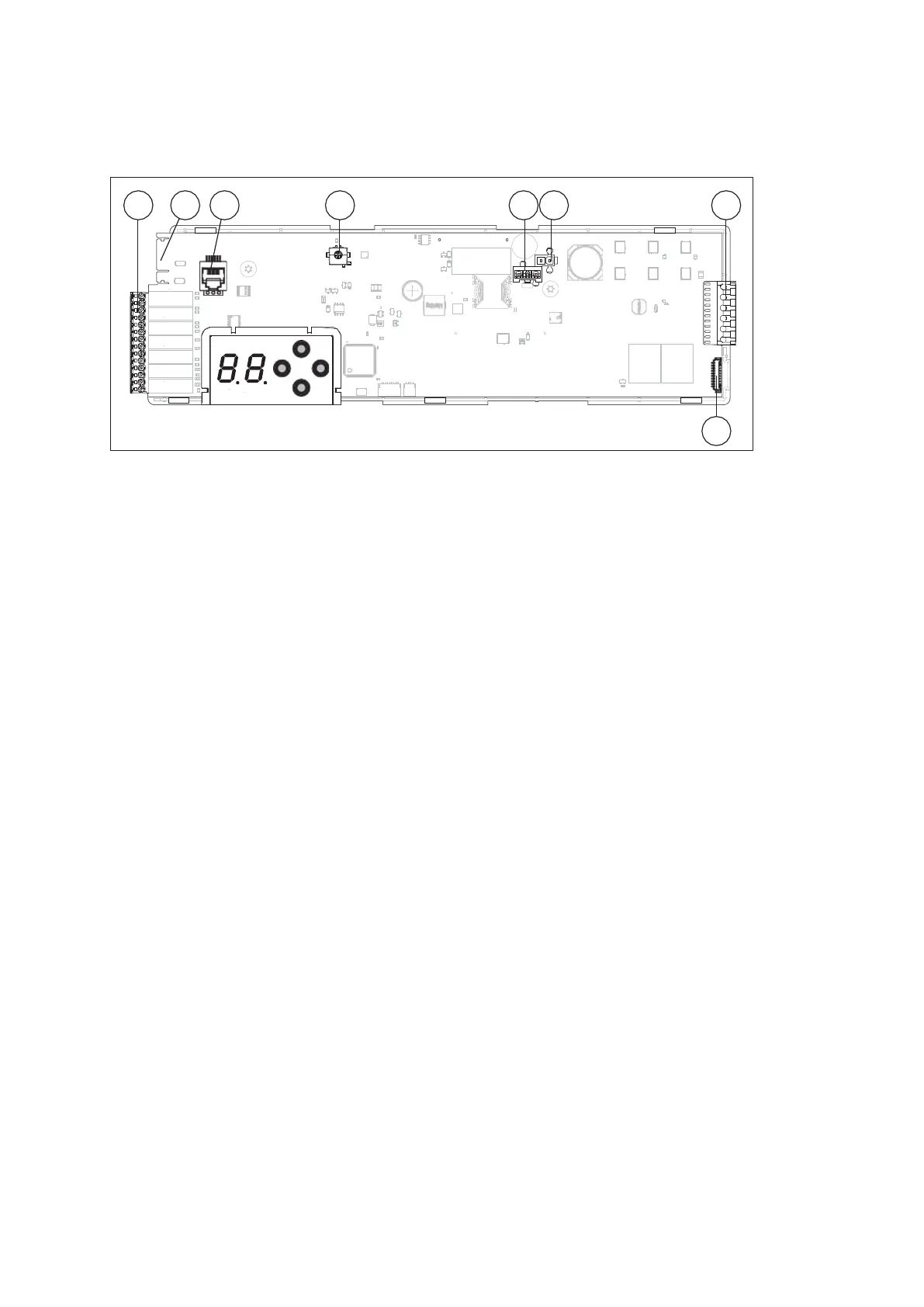
Terminal layout
6 Terminal layout
1. Terminal layout of the control board
1 2 3 4
5 6 7
8
Fig. 8 0
(1) Terminal block
(2) Operator locking device connection
(3) COM port
(4) CAN BUS port
(5) Power supply connection
(6) Battery pack connection
(7) Drive connection
(8) Hall effect sensor connection
ES 250 PRO Easy
2024-03
48
ES250ProEasy Installation Manual



 To Next Page