CAN BUS system (only for EPS CAN)
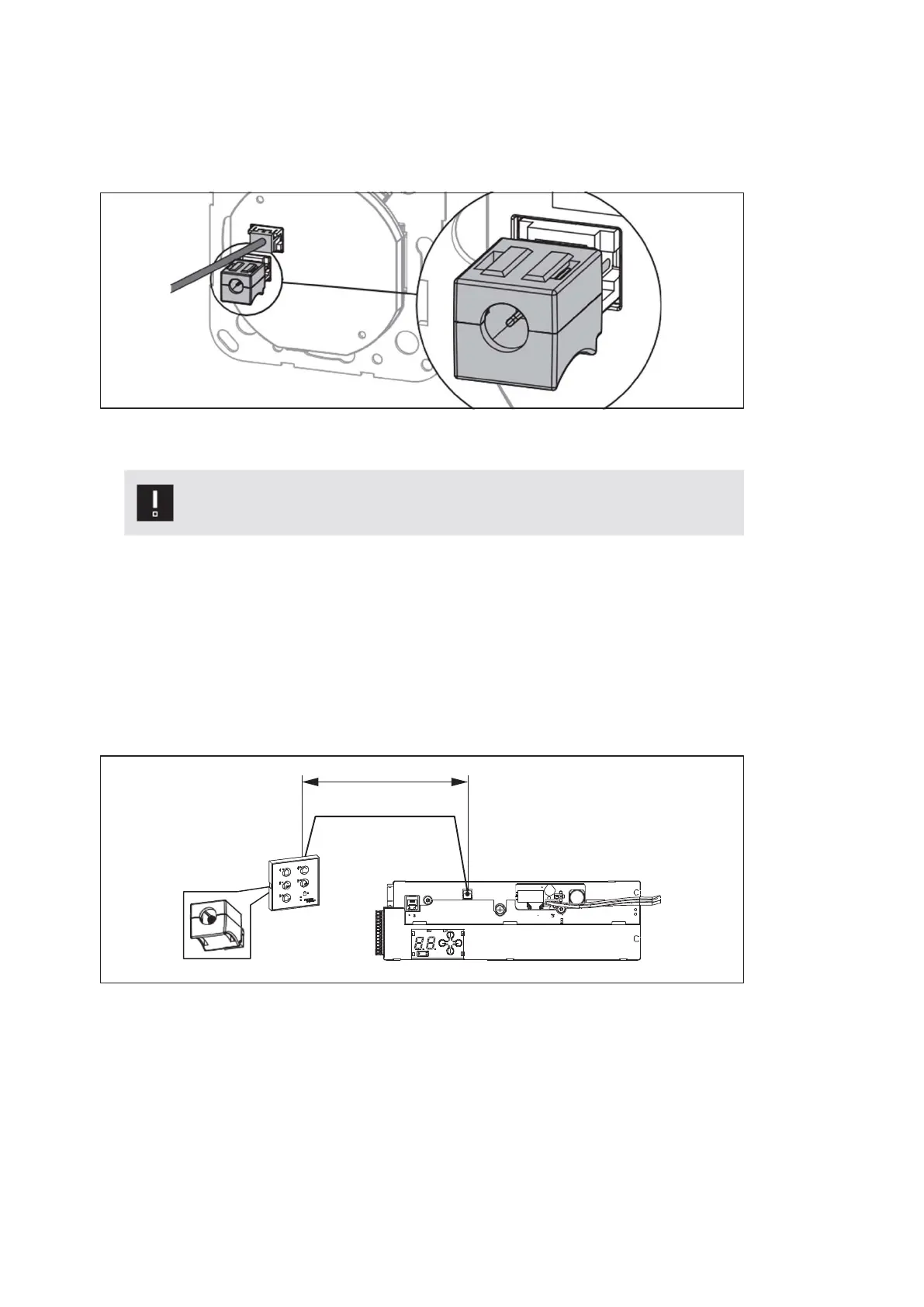
5.2.1 Terminating resistor
• The CAN BUS components either have a switchable terminating resistor or the
terminating resistors are connected t o the free CAN BUS connection.
Fig. 78
5.3 Connecting a CAN BUS component
Attention
The CAN BUS components must not be connected under live voltage!
1. Remove the terminating resistor from the required CAN BUS connections on
the operator control unit and retain.
2. Connect the EPS CAN with the CAN BUS cables.
3. Drill the holes for the CAN BUS cable with a diameter of 8 mm.
4. In addition to the cable, also insert a terminating resistor into the EPS CAN.
5.3.1 Connecting the operating mode switch
Fig. 79
max. 30 m
ES 250 PRO Easy
2024-03
47
ES250ProEasy Installation Manual



 To Next Page