dormakaba USA Inc. System User Guide 7040.0321 | 7
2 Typical System Layout (Single & Multi)
The following sub-sections review safe lock system components with related diagrams. Refer to each product’s individual
documentation for more detailed information on hardware installation and proper device usage.
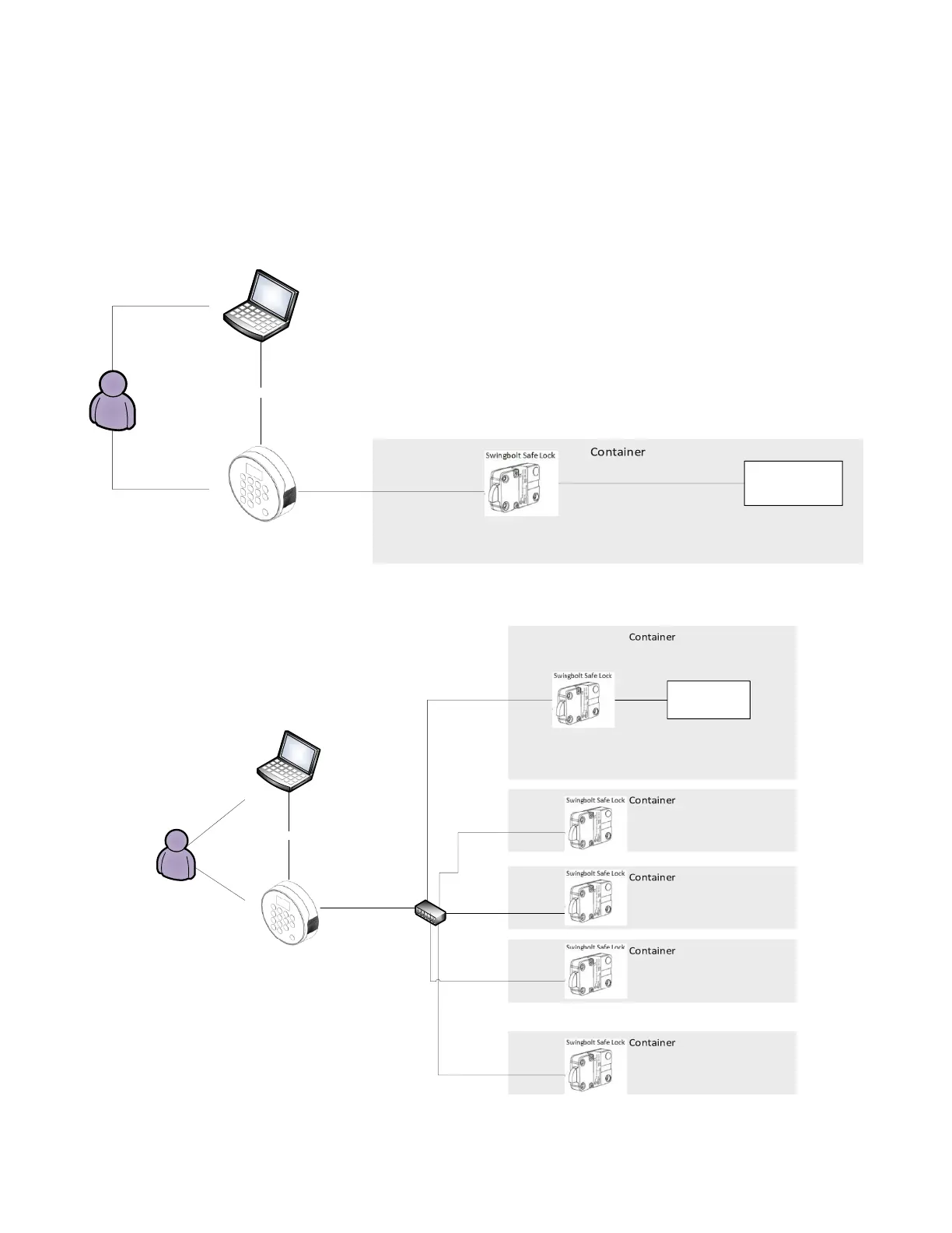
The following diagrams (Figures 1 and 2) show completed system layouts for both single and multi-lock systems. Please
note that your system may not include all components shown.
Figure 1 – Single Lock System





 To Next Page