Issued July 2024
Body Controller Softw are
Copyright 2024, The Heil Co.
Printed in the U.S.A.
Body Controller Software
145
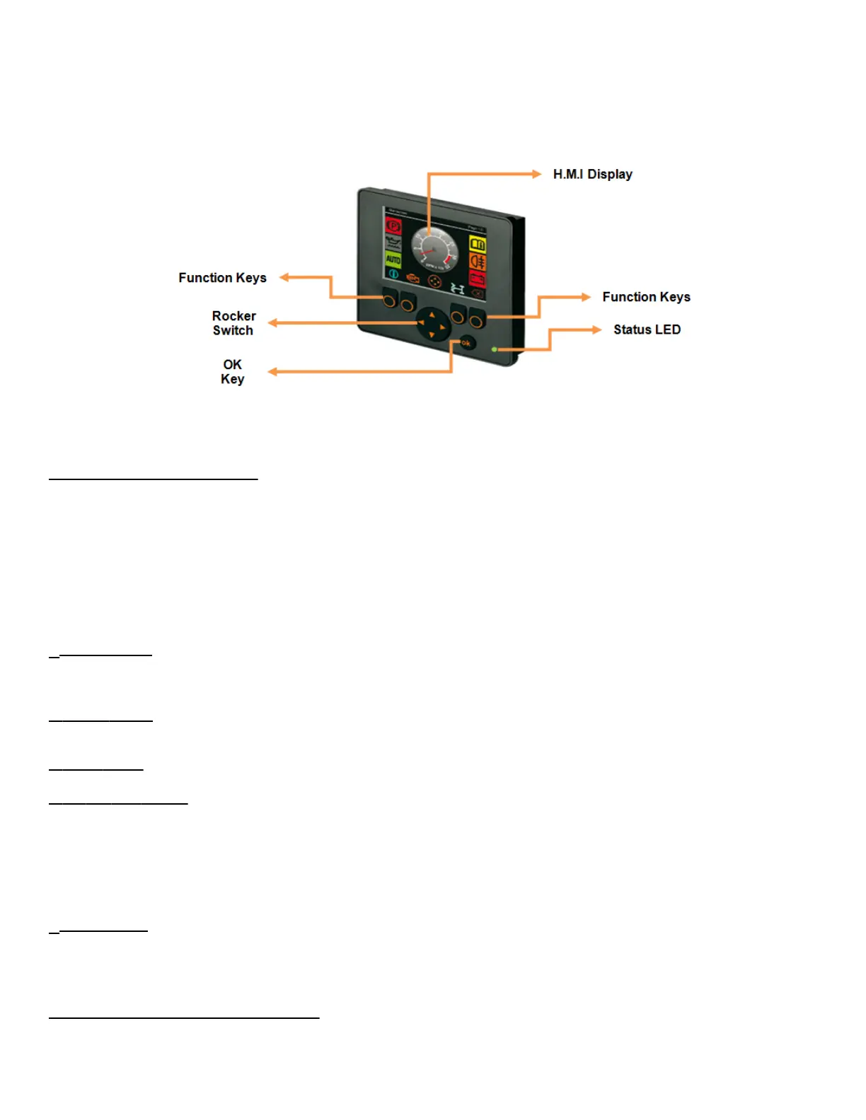
Fig: INSIGHT Display Unit
5.05.01: Operating Elements
INSIGHT is a basic 2.8” color Display unit, which consists of 4 freely programmable backlit function keys and a H.M.I (Graphic) display
terminal:
The display is fitted with the following operating elements:
1. 4 Function Keys with Pressure points
2. 1 Rocker switch (KEY_UP / KEY_DOWN / KEY_LEFT / KEY_RIGHT)
3. Status LED’s (Function display with 2-colour LED (red/green)).
4. OK Key Push Button
5. H.M.I Display.
1. Function Keys: There will be 4 backlit freely programmable function keys available in INSIGHT. These can be used as password
protection keys (for Ex: key from left to right can be considered as “1 – 2 – 3 - 4 or A – B - C – D”) or these function keys can be
assigned specific function / Operation.
2. Rocker Switch: The Rocker switch may be used for cursor movement function (Up / Down / Right / Left). This can also be used for
navigation purpose from current page to next page or to the previous page.
3. Status LED’s: It has 2 color LED (Red / Green). Refer section 5.05.04 for more details.
4. OK Key Push Button: This key is used for enabling or disabling the Input /Output from H.M.I.
For Ex: When a particular Input / Output bit is selected using Rocker switch, the OK key can be used to turn ON / OFF that particular bit.
Once a particular bit is turned ON / OFF, the respective bit color will be changed from Red to Green or vice versa, which will be displayed
on the H.M.I terminal as shown in the figure below.
Note: By holding the OK button down for 10 seconds and entering “4 – 3 – 2 – 1” we can get access to the screen to Reset the Arm
Cycle counts and Packer cycle counts.
5. H.M.I Display: This is used for displaying the current status of the Input / Output, Engine Run Speed, Temperature, Auto/Manual
mode etc.
This can be programmed for graphically representing a process. This can also be used for changing the set points for Analog values.
Following figure shows current state of the Input / Output variables.
5.05.02: Display Operating States: