COM 2
ADD
COM 1
RT
AL
SD
24 V
M1
14/40 15/40
Initialisation - SD-L-F1
- First, roughly align the infrared beam with the reflector using the laser.
- Slide the slide switch to the left (Align) to switch on the laser.
- Use navigation buttons to adjust the laser dot on the reflector.
- Move the slide switch to the right (Operate) to start the automatic alignment of the infrared beam.
- Alignment status LEDs flash during alignment:
- LED on right (green) flashes permanently (alignment in progress).
- LED on left (green) flashes to indicate the alignment phase (phases 1 to 4).
- LED in centre (orange) flashes if alignment fails. The number of flashes indicates in which phase
alignment failed (phases 1 to 4).
- If alignment fails, ensure that the reflector is installed correctly and that there are no reflective
surfaces in the area of the reflector or near the beam path.
- Then re-attempt alignment.
- The green LED flashes for 10 seconds after having successfully completed alignment.
- The detector’s green status LED flashes every 10 seconds.
Slide switch
/ OperationAlignment
DIP switch
Do not change factory settings!
Navigation buttons
to set the laser dot
Laser
Alignment LEDs
Left
(green)
Middle
(orange)
Right
(green)
Status indicator:
Normal mode:
green LED flashes every 10 seconds
Fault:
orange LED flashes every 3 seconds (internal fault)/
every 5 seconds (“AGC/alignment“ fault)/
every 10 seconds (“Signal high/low“ fault)
Alarm:
red LED flashes every 5 seconds
Status indicator
Reflector
ONOFF
= LED lights up = LED flashes
Emergency ventilation**:
Ventilation alarm, radio connection disturbed
Shaft temperature too high
Fault*
Fire alarm
green red yellow
Description
= LED does not light up
blue
System "OK“
Hygienic ventilation:
Manual opening (ventilation button)
Automatic opening (RTR)
* Central unit is only partially operational, contact customer service.
** Flap cannot be closed by manual ventilation button.
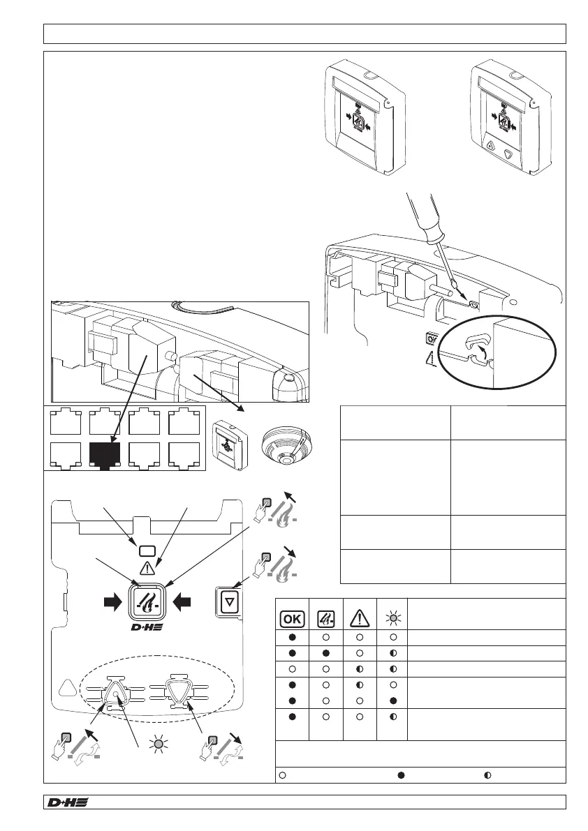
Mounting - Smoke vent button RT 45-L-RJ / RT 45-RJ
- The smoke vent button (RT 45L-RJ / RT 45-RJ)
can be used to initiate manual venting and reset
an alarm.
- Up to 8 smoke vent buttons can be connected in
series.
- Smoke monitoring of the main evacuation level is
provided by a point detector, which can be
connected directly to the RT 45-RJ.
- A monitoring resistor is used to monitor the line.
- Only if another smoke vent button or a point
detector is connected to the RT 45-RJ, the PCB
jumper J1 must be removed.
- Connect the smoke vent button to the „RT“ socket
on the central unit.
Operation OK
RESET
ALARM
Fault
Alarm
Ventilation OPEN
... -LT
OK
RT 45-L-RJRT 45-RJ
Last RT:
Do not remove J1
All other RTs:
remove J1
J1
<or>
99.829.07 1.2/06/2399.829.07 1.2/06/23
AIO Basic AIO Basic
English
English