max. 70 m max. 36 m
max. 70 m
COM 2
ADD
COM 1
RT
AL
SD
24 V
M1
18/40 19/40
Power supply 230 V AC, 50 Hz (195 ... 253 V AC)
Rated power 9,2 VA
Rel. humidity (operation) 20 %RH ... 90 %RH
Temperature range -5 °C ... +40 °C
Ingress protection IP 32
Protection class II
Ventilation connection max. 30 V DC / 1 A (resistive Load)
Signal relay max. 30 V DC / 0,1 A (resistive Load)
Emergency call input 0 ... 30 V DC / max. 7 mA / typ. trigger treshold 4 V DC
Measuring range CO2 level 400 ppm ... 2.000 ppm (±150 ppm)
Measuring range temperature -5 °C ... +40 °C (±1,5 °C)
Measuring range rel. humidity 0 %RH ... 100 %RH (±10 %RH)
Technical Data - LST-CO2
Deleting all LST-CO2:
1. Press and hold the teach button on the central unit until you hear a
long audible signal. This signals that all LST-CO2 have been deleted.
Teaching the LST-CO2:
1. Connect the LST-CO2 to 230 V AC.
2. After 5 seconds, press the teaching button on the central unit until
you hear a short audible signal. The audible signal repeats and the
central unit is in teach mode.
3. Press the Set button on the LST-CO2 for 2 seconds.
4. The green “radio” LED on the LST-CO2 lights up green for 3
seconds and the central unit acknowledges this with a short
audible signal. LST-CO2 calibration has been completed.
If the "radio” LED flashes red, once again press the set button on
the LST-CO2.
5. Then briefly press the teaching button on the central unit. The
central unit as well as LST-CO2 are in normal function mode.
Teaching several LST-CO2:
1. Configure one LST-CO2 as master and all the others as slave
(see DIP switch assignment).
2. Only one LST-CO2 must be defined as the master.
Select any LST-CO2 as the master and make sure this has been
clearly labelled.
3. Teach each LST-CO2 (see above).
4. Then briefly press the teaching button on the central unit. The
central unit as well as all LST-CO2s are in normal function mode.
Initialisation - LST-CO2
LED:
Radio
CPL-B
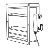
„set“ button
LST-CO2
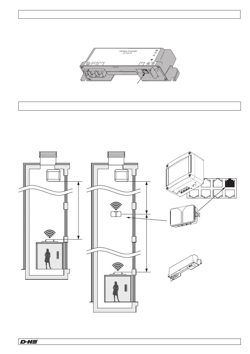
Mounting - Lift Status Repeater LSR
In systems with a radio distance between the LST-CO2 and the CPL-B central unit of more than 70 m, the radio
signal must be amplified by a lift status repeater (LSR).
The LSR is installed in the shaft.
Connect the RJ45 cable of the LSR to the "24 V" socket on the central unit.
If the socket is occupied, use a RJ45 switch.
As a rule, if the emergency call button in the car is pressed, it is frequently possible to tap into emergency
potential on the car roof, often as feed voltage for an emergency bell that is routed to the LST-CO2 by an RJ11
patch cable. This emergency feed voltage is exclusively forwarded using two connection wires and can be
between 4 and 30 V DC. In this process, potential assignment is irrelevant.
Identifying a lift fault with trapped persons
Connection "Emergency call"
CPL-B
LSR
LST-CO2
99.829.07 1.2/06/2399.829.07 1.2/06/23
AIO Basic AIO Basic
English
English
Teach button