8/40 9/40
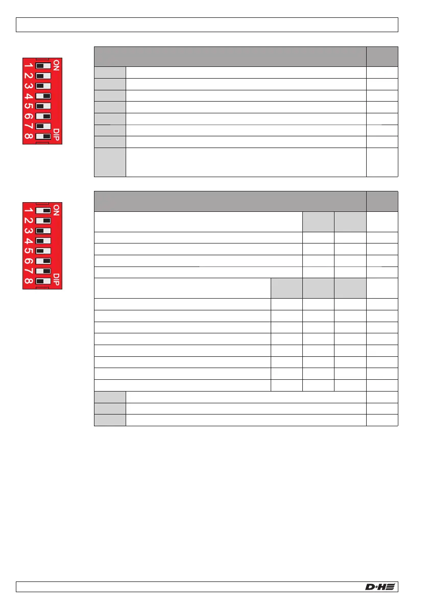
DIP switch settings - CPL-B
Alarm delay, shaft group (60 s)
Shaft group: Ventilation time limitation
Shaft group: Group fault = alarm
Line port 1 shaft detector: Active
Service timer: ON / OFF (486 days)
Service timer is activated as soon as it is switched from
OFF state (min. 3 sec. duration) to ON.
S1
Factory settings
Normally closed contact signalling relay -
fault message at RJ45 socket COM 1
Fault in shaft detector and fault group M1
Internal temperature sensor: trigger temperature fault at all lines at 72°C
Temperature-dependent ventilation: ON/OFF
Temperature sensor: Ventilation threshold: OFF= ca. 30°C/ON = ca. 35°C
Signalling relay normally open contact/normally
closed contact - fault/alarm at RJ45 socket COM 2
General malfunction (normally closed contact)
Shaft fault: (NC contact) line or group
RT fault: (normally closed contact)
General fault (normally open contact)
Line alarm: (Normally open contact) shaft
Alarm: (Normally open contact) stairwell
S2
Factory settings
Technical Data - CPL-B
Power supply
Rated power
Stand-by operating
230 V AC, 50 Hz (195 ... 253 V AC)
55 VA
< 20 VA
24 V DC
<0,5 Vpp; < 1%, load-dependent
Monitoring:
Output current
Mode of operation
Alarm / Ventilation:
Output current
Mode of operation
700 mA
Short-time duty, 30% ED
Number of lines / groups*
Fire detectors per line
SHEV buttons per line
Line voltage
1/1
max. 14 pcs.
max. 8 pcs.
15 V DC (12 ... 17 V DC)
Temperature range
Ingress protection
Protection class
-5 ... +40°C
IP 30
II, with fuctional ground
Housing:
Material
Colour
Dimensions WxHxD
Plastic (Polycarbonate)
white
172 x 151 x 95 mm
* D+H Highspeed (HS) drives will be supported.
An overdue maintenance of the system will be
indicated by the control panel after about ca. 14 to
16 months.
The yellow LED in the smoke vent button (RT-45L-
RJ / RT-45-RJ) will start flashing.
A malfunction of the smoke vent system will be still
indicated by the extinction of the green LED in the
smoke vent button (RT-45L-RJ / RT-45-RJ).
The service timer is reset using DIP switch S1.8.
To carry out the reset, set the DIP switch to OFF
for at least 3 seconds, then set it to ON again.
If the service timer is not needed, set DIP switch
1.8 permanently to OFF.
This switches off the service timer.
Service timer
99.829.07 1.2/06/2399.829.07 1.2/06/23
AIO Basic AIO Basic
English
English
Observe regulations for danger warning systems
VDE 0833, guidelines for electrical systems VdS
2221, VDE 0100, DIN 18232 for smoke and heat
vent systems, regulations of the local fire-brigade
and of EVU for connection to mains supply.
Important regulations
Declaration of Conformity
We declare under our sole responsibility that the
product described under “Technical Data” is in
conformity with the following :regulations
2014/30/EU, 2014/35/EU, 2011/65/EU
S.I. 2016/1091, S.I. 2016/1011, S.I. 2012/3032
Technical file at:
D+H Mechatronic AG, D-22949 Ammersbek
Dirk Dingfelder Maik Schmees
CEO CTO
01.06.2023