26/40 27/40
Status indicators (maintenance level 1)
COM 2
ADD
COM 1
RT
AL
SD
24 V
M1
Ventilation relation LST
(DIP S2.1 ON/OFF)
Not assigned
V
entilation relation LST
(DIP
S2.2 ON/OFF)
Ventilation duration LST
(DIP S2.3 ON/OFF)
V
entilation duration LST
(DIP
S2.4 ON/OFF)
Ventilation intervall LST
(DIP S2.5 ON/OFF)
V
entilation intervall LST
(DIP
S2.6 ON/OFF)
Not assigned
Not assigned
Not assigned
Not assigned
Not assigned
LST-CO2 logged in
Actuation counter M1
(flashing 5th digit)
Actuation counter M1
(flashing 4th digit)
Maintenance level ON
(Flashing 1x Level 1)
(Flashing 2x Level 2)
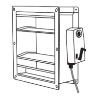
Function test - Ventilation elements JK-180 / JK-190
1. Check ventilation element louvres have closed and are airtight (visual
inspection). Replace the entire ventilation element if seals are severely
damaged and can no longer guarantee the ventilation element is airtight
when closed.
It is not possible to replace the louvres’ rubber seals.
2. JK-180 / JK-190 ventilation element drives have been designed for a
minimum of 60,000 “OPEN/CLOSED” cycles.
Once this number of cycles has been exceeded, it may be possible that the
return spring or mechanical drive system fails.
In this case, replace the return spring motor!
Read number of cycles (Maintenance level 1 status indicator, "actuation
counter M1" LEDs). Enter number of cycles in maintenance protocol. It is
not possible to reset the counter to zero.
If the motor is replaced, write down the counter figure in the maintenance
manual upon commissioning. Correctly document replacement.
Example: Red LED (N) flashes for 5-digit figure (e.g. 2x = 20,000)
Yellow LED (O) flashes for 4-digit figure (e.g. 7x = 7,000)
The number of actuations is 27,000.
JK-190
JK-180
Maintenance and cleaning
Once a year by a specialist company, who is authorized by the appliance manufacturer.
Renew test badge, keep log book.
Inspection and maintenance has to be carried out according to D+H maintenance notes.
Only original D+H spare parts may be used. Repair is to be carried out exclusively by D+H.
Maintenance work is only allowed when the device is in a de-energized condition!
Wipe away debris or contamination with a dry, soft cloth.
Do not use cleaning agents or solvents.
Preparation:
- Use personal protection equipment.
- Inspect place of use.
- Inform person responsible for the building about maintenance work.
- If the system has been linked to an on-site fire alarm system, have the corresponding fire alarm system
strand deactivated.
- Attach information signs to each shaft door of the lift.
Carry out the following checks:
- Visual inspection for damage, tightness and debris.
- Check unobstructed distance in shaft between lift components and ventilation element as per EN 81-20.
- Check protected areas between car and ventilation element as per EN 81-20.
- Function test of the system components.
- Check all relevant power supply units.
- Logging of proper maintenance execution and labelling according to specifications.
Fault test of the components:
- Pull out all components connected via RJ45 plugs one after the other.
- A fault, possibly with an alarm, is immediately indicated on the RJ45 socket LEDs of the central unit and
on the smoke extraction button (if present).
- Reconnect the plug. The fault disappears. If necessary, reset an alarm with the reset button.
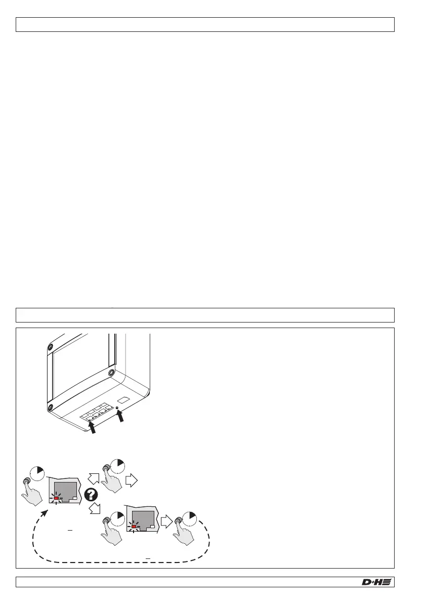
CPL-B
LED „RM“
Reset Button
1x
Maintenance
level 1
SD
2x
Maintenance
level 2
SD
Normal operation -
Maintenance level
deactivated
~
3
Sec.
~
1
Sec.
~
1
Sec.
~
3
Sec.
Maintenance mode / Alarm Reset - CPL-B
1. Press the Reset button for 3 seconds
(maintenance level 1 / LED "SD" flashes 1x/sec.)
System runs LED test, all LEDs at the ports
light up for approximately 4 seconds.
Any active alarms are reset.
The ventilation element opens.
Check the number of ventilation element
cycles "M1" (see next page).
2. Either press the reset button for 1 second
(maintenance mode is deactivated).
or
Press the reset button again for 3 seconds
(maintenance level 2 / LED "SD" flashes
2x/sec). The ventilation element closes and
remains closed (e.g. blower door test).
3. Press the reset button for 1 second
(maintenance level 1 is activated again).
The ventilation element opens again.
4. Press the reset button again for 1 second
(maintenance mode is deactivated).
The central unit is back in normal operating
mode.
99.829.07 1.2/06/2399.829.07 1.2/06/23
AIO Basic AIO Basic
English
English
Following tests must be carried out in the course of
maintenance:
- Outside examination / inspection of system
components
- Checking of all relevant power supply units
- Functional testing of connected system
components
- Record of competent carrying-out of
maintenance, and designation according to
directions
Examination:
- Check all appliances and cable connections for
outer damage and dirt accumulation.
- Fire detectors, smoke vent buttons, smoke vents
and so on must not be impaired in their function
by goods in storage or structural changings.