30/40 31/40
230 V mains voltage
interrupted
Check mains fuse
in fuse box
Memory fault/error
in program sequence/
oscillator fault
Restart control panel
If applicable, contact service
“Communication” LED lights up
Interrupted radio connection to
LST / LSR
“Service timer” LED lights up permanently
Set DIP switch 1.8 to OFF for
a minimum of 3 seconds
The “Central unit” and “Mains voltage” LEDs have not been mentioned here and in normal mode they light up
green, thus not indicating a fault.
“Service timer” LED flashes in normal mode.
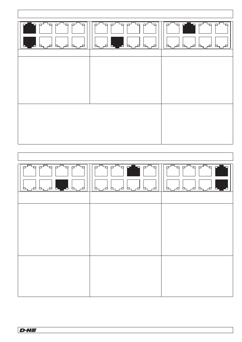
Troubleshooting - Internal fault indicators Troubleshooting - External fault indicators (AL, SD, RT, COM 1)
Troubleshooting - External fault indicators (ADD, COM 2, 24 V, M1)
COM 2
ADD
COM 1
RT
AL
SD
24 V
M1
COM 2
ADD
COM 1
RT
AL
SD
24 V
M1
COM 2
ADD
COM 1
RT
AL
SD
24 V
M1
COM 2
ADD
COM 1
RT
AL
SD
24 V
M1
COM 2
ADD
COM 1
RT
AL
SD
24 V
M1
COM 2
ADD
COM 1
RT
AL
SD
24 V
M1
Troubleshooting - Alarm signal SD-L-F1 (set point function)
99.829.07 1.2/06/2399.829.07 1.2/06/23
AIO Basic AIO Basic
English
English
Run the setpoint function if an alarm notification is displayed during a fault test:
quickly covering the prism must lead to a fault at SD-L-F1 during installation of SD-L-F1. SD-L-F1 detects
this using the very low signal level (< 15 %) that is triggered if the retroreflector is covered quickly (within
2 seconds).
In some installations SD-L-F1 indicates a FIRE signal rather than an ERROR signal upon quickly
covering the prism. This is based on the fact that the installation has other “scattering”, reflecting surfaces
in the vicinity of the beam path that are influencing the measurement.
The Setpoint function is a software function within SD-L-F1 with which the system can compensate for
scatter reflections.
Adjusting the Setpoint:
Quickly cover the prism after having installed and equipped the detector. If SD-L-F1 displays a FIRE
signal rather than a FAULT signal, once again remove the cover from the prism. Then simultaneously
press and hold the left and right direction buttons on SD-L-F1. The middle LED above the SD-L-F1
buttons flashes 3x. Then release the buttons. A further fault and fire test is subsequently necessary for
verification.
Status (ambient temperature)
Fault/status (motor group)
LED (yellow) at
- LST-VOC temperature signal
> 35 °C / 35 °C
- Ventilation interval active
- LED (red = ventilation alarm) at
- communication fault (radio)
- Emergency call button triggered
- Permissible air quality
> 1500 ppm
LED (yellow = signal) at
- general malfunction
LED (red) at
- ambient temperature in shaft
or in machine room > 30 °C /
< 72 °C
LED (flashing red) at
- ambient temperature in central
unit > 72 °C
LED (yellow) at
- RJ45 plug connection to motor
interrupted
- Central unit fuse
motor faulty
LED (red) at
- OPEN signal: ventilation
element not closed
- At signal ventilation (yellow):
wait for interval to end
- For ventilation alarm (red):
eliminate corresponding cause
For system test temporarily
switch
DIP 2.7 = OFF
DIP 2.8 = OFF
.
Restore delivery state after
system test!
Test:
- Motor connection
- Central unit fuse motor
LED (yellow) interrupted
- at RJ45 plug connection
- Point smoke detector
removed
- Fault message from Beam
regulator
- Connection to FAS
interrupted
LED (yellow) interrupted
- at RJ45 plug connection
- Operation panel removed
- Point smoke detector in
stairwell removed
- Circuit board jumper removed
from last RT circuit board
LED (yellow) at
- system component or line
connection demonstrating
isolation fault
- Electrical connection with
protective earth or ground
potential
Test:
- connection/cable of smoke detector components
- Controller components
- Beam settings
Test:
earth connection at components
or cable connection.
For instance, proceed as follows
for localisation: successively
unplug RJ45 plugs and monitor
LED in the process.