3/402/40
Table of contents
Intended use
- The AIO basic system is used in lift shafts to detect
fires with developing smoke and for ventilation.
- Only for inside mounting
Operating voltage 230 V AC!
Risk of injury from electric shock!
- Connection has to be carried out only by an
authorized electrical specialist
- Only for inside mounting
- Just use unchanged original D+H parts
Caution Falling Hazard!
- Always secure ventilation elements properly
against falling down the shaft.
The following protective equipment must be worn:
- Hard hat
- Safety goggles
- Safety shoes
- Full-body safety harness
- Protective gloves
- Hearing protection
Safety notes
Application example
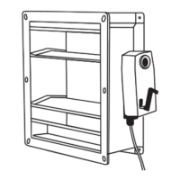
Ventilation flap (JK)
with spring return motor
Smoke detector in the lift shaft
Lift Status Transmitter (LST-CO2)
Smoke vent button (RT-45L-RJ / RT-45-RJ)
Smoke detector at main evacuation level
Connection to lift controller
Notice:
The system here has not been illustrated with all
available components.
If available, install the timer and thermostat in the
vicinity of the central unit.
Install the key switch in coordination with the
operator.
Product overview and mounting
Intended use .............................................................................................................................................3
Safety notes ..............................................................................................................................................3
Application example..................................................................................................................................3
System components overview ..................................................................................................................4
System components description ...............................................................................................................5
Overview control panel - CPL-B................................................................................................................6
LED indicators- CPL-B..............................................................................................................................7
RJ45 connections and status LEDs ..........................................................................................................7
DIP switch settings - CPL-B......................................................................................................................8
Technical Data - CPL-B.............................................................................................................................9
Declaration of Conformity .........................................................................................................................9
Service timer .............................................................................................................................................9
Important regulations ................................................................................................................................9
Mounting - Weather protection HVC, HVL, ALAS ...................................................................................10
Mounting - Ventilation flap JK 180, JK 190 ........................................................................................10-11
Mounting - Control unit CPL-B ................................................................................................................12
Mounting - Point detector in the lift shaft PD-RJ-AIO..............................................................................12
Mounting - Infrared detector SD-L-F1 .....................................................................................................13
Initialisation - SD-L-F1 ............................................................................................................................14
Mounting - Smoke vent button RT 45-L-RJ / RT 45-RJ ..........................................................................15
Mounting - Lift Status Transmitter LST-CO2 ...........................................................................................16
DIP switch settings - LST-CO2 ...............................................................................................................17
Technical Data - LST-CO2 ......................................................................................................................18
Initialisation - LST-CO2 ...........................................................................................................................18
Identifying a lift fault with trapped persons .............................................................................................19
Connection and setup
Mounting - Lift Status Repeater LSR ......................................................................................................19
Connection - RJ45 sockets .....................................................................................................................20
Connection - 230 V power supply ...........................................................................................................21
Connection - M1 output...........................................................................................................................21
Connection - General status signals COM 1...........................................................................................22
Connection - Lift shaft control COM 2.....................................................................................................23
Connection - FAS input ...........................................................................................................................24
Blower Door Test.....................................................................................................................................25
Disposal ..................................................................................................................................................25
Maintenance
Maintenance and cleaning ......................................................................................................................26
Maintenance mode / Alarm Reset - CPL-B .............................................................................................26
Status indicators (maintenance level 1) ..................................................................................................27
Function test - Ventilation elements JK-180 / JK-190 .............................................................................27
Function test - Smoke detector SD-L-F1 ................................................................................................28
Function test - Smoke detector PD-RJ-AIO ............................................................................................28
Function test - Lift Status Transmitter LST-CO2 .....................................................................................29
Function test - Smoke vent button RT 45-RJ ..........................................................................................29
Troubleshooting
Troubleshooting - Internal fault indicators ...............................................................................................30
Troubleshooting - Alarm signal SD-L-F1 (set point function) ..................................................................30
Troubleshooting - External fault indicators..............................................................................................31
Troubleshooting - Ventilation element does not close .......................................................................32-33
Troubleshooting - Ventilation element does not open .............................................................................34
Troubleshooting - Malfunction of the LST-CO2 ......................................................................................35
Troubleshooting - LSR malfunction.........................................................................................................36
Mounting material
Mounting material ...................................................................................................................................37
Notes .................................................................................................................................................38-39
99.829.07 1.2/06/2399.829.07 1.2/06/23
AIO Basic AIO Basic
English
English
WARNING
Read all safety warnings, instructions, illustrations
and specifications provided with this product.
Failure to follow all instructions listed below may
result in electric shock, fire and/or serious injury.
Save all warnings and instructions for future
reference.