Ceiling and wall attachment
Dr. Mach
Lamps and Engineering
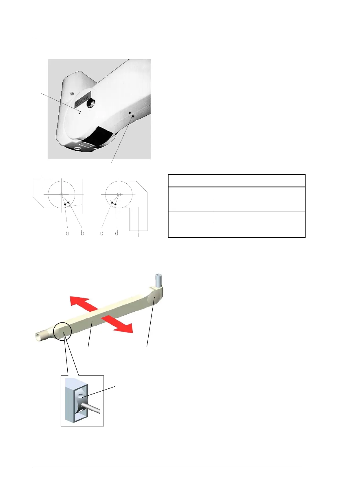
8.3.2 Space spring arm
The adjustment is carried out as follows:
Dismantle the plastic cover on both sides. Remove
the four screws X, two screws Y on the top side and
another two screws Y on the lower side of the
spring arm and take the two halves apart.
Remove the two inside retaining rings of the stop
pin.
Extract the stop pin and re-insert it in the required
position. Damage can be caused, if the arm is used
without the stop pin.
Affix the two retaining rings. Replace the plastic
cover (four sealing flaps in the guide), engage these
and secure the cover with the eight screws X and Y.
Y
X
Position Range of movement
a 40° downwards
b 20° downwards
c 40° upwards
d 20° upwards
8.3.3 Central spring arm
Central spring arm (since 2000)
At delivery the spring arm is set in the horizontal
position.
The vertical movement of the spring arm can be
enlarged up to 45 degrees upwards.
Attention!
Power off the on-site power supply and protect
it from being switched on again.
• Power off the pendant system / pull out the
power plug and protect the pendant system
from being switched on again.
• Remove the two Philips screws 4 and take off
the covers 3.
• At the position marked X you can see the ad-
justing nut 5.
• Adjust the nut 5 with the enclosed metal pin.
• Mount the two covers 3 and fix them with the
two Philips screws 4.
• Check the firm seating of the covers 3.
X
3 4
5
59500001 Edition 06 11.03.2003 / Bak Page 40/48