32 DR
®
TRIMMER/MOWER
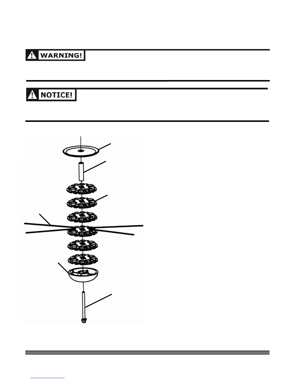
Reassembling the Mow-Ball
™
Support Assembly
BEFORE PERFORMING ANY MAINTENANCE PROCEDURE OR INSPECTION, STOP THE ENGINE, WAIT FIVE
(5) MINUTES TO ALLOW ALL PARTS COOL. DISCONNECT THE SPARK PLUG WIRE, KEEPING IT AWAY FROM
THE SPARK PLUG.
IMPROPER INSTALLATION CAN CAUSE DAMAGE TO THE TRIMMER BEARINGS. FOLLOWING THESE
DIRECTIONS CAREFULLY WILL PROTECT YOUR MACHINE FROM DAMAGE. REASSEMBLE THE
COMPONENTS IN THE ORDER SHOWN IN FIGURE 21.
1. Position the Backup Plate with the lip of the curve
facing up (Figure 21).
2. Stack the Line Plates on top of one another with the
bumps on the bottom locking into the grooves on
top of each Plate.
3. Insert the Line Plate Standoff onto the center of the
stack (Figure 21).
4. Place the head of the Mow-Ball
™
Support Bolt so it is
sitting in the groove at the bottom of the Mow-Ball
™
Support.
5. Hold the bolt head in place with your finger and turn
the Mow-Ball
™
Support Assembly clockwise until it is
finger tight.
6. Insert the Head Locking Tool or screwdriver as
shown in Figure 19 on page 31 and tighten the
assembly securely by turning the Mow-Ball
™
Support
Assembly counterclockwise.
NOTE: If there is a space between any of the components of
the assembled Mow-Ball
™
Support, repeat the stacking
procedure.
Figure 21
Backup Plate
(curve faces up)
Line Plate (6)
Line Plate Standoff
Mow-Ball™ Support
Mow-Ball™ Support Bolt
Cutting Cord