REPLACEMENT PROCEDURES (continued) NM2C
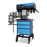
4.21 Display Arm Assembly
This procedure applies to both the adjustable arm and the short arm.
The display arm assembly includes a support plate that attaches to the left
side of the machine with socket head screws that thread into the bellows box
and ventilator box. Before removing the display arm from the machine, the
Datagrip and remote display assembly must be removed from the outboard end
of the arm. Figure 4-21 shows a typical display arm mounting arrangement.
Figure 4-21A shows the cable routing arrangement for the adjustable arm, and
Figure 4-21B shwos the cable routing arrangement for the short arm.
Refer to Figure 4-21C for installations with an optional patient line boom arm.
4.21.1 Turn the System Power switch to STANDBY.
CAUTION: Do not plug or unplug remote display with power applied.
4.21.2 Disconnect the remote display and Datagrip cables from their ports
on the underside of the ventilator box.
4.21.3 Remove the screws holding the cable clamps along the display arm
and separate the cables from the display arm.
4.21.4 Remove the screws holding the cable clamps to the underside of the
bellows box and the underside of the ventilator box.
4.21.5 Remove the plastic cap at the end of the display arm to expose the
Datagrip assembly mounting screw.
4.21.6 While holding the Datagrip assembly, loosen the mounting screw
until the assembly separates from the display arm.
WARNING: Do not attempt to disassemble the display arm sections. Release
of the internal spring may cause injury to personel.
4.21.7 While holding the display arm, remove the six screws holding its
support plate to the side of the machine.
......................................................................
NOTE: If the replacement display arm hardware was not pre-assembled,
refer to Service Procedure SP00114 for assembly details.
4.21.8 Hold the replacement display arm assembly in place and secure the
support plate to the machine with the screws that were previously
removed. If the machine is equipped with a manual
sphygmomanometer, the longer screw is used to secure the gauge
mount at the lower front corner of the support plate.
Rev. B
4-64
RETURN TO CD-ROM TABLE OF CONTENTS
RETURN TO THIS MANUAL'S TABLE OF CONTENTS
 Loading...