31
8-17
8-16
Step 3
1
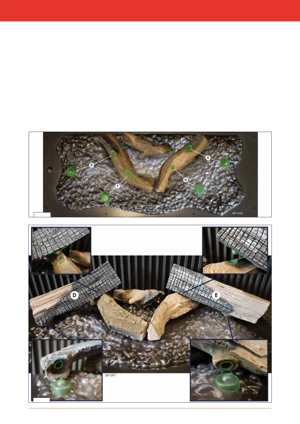
Place log D on the positioning cam on the left on the glow bed. The positioning cam at the bottom right on log D falls
into the recess on log B (g 8-16 and 8-17).
1
Place log E on the positioning cam on the right on the glow bed. The positioning cam at the bottom left on log E falls
into the recess on log C (g. 8-16 and 8-17).
1
Place log F on the positioning cam on the front left of the glow bed. This causes log F ts into a recess on log B
(g. 8-16 and 8-18).
1
Place log G on the positioning cam on the front right of the glow bed. The positioning cam at the bottom left on log G
falls into the recess on log C (g 8-16 and 8-18).
Installation manual