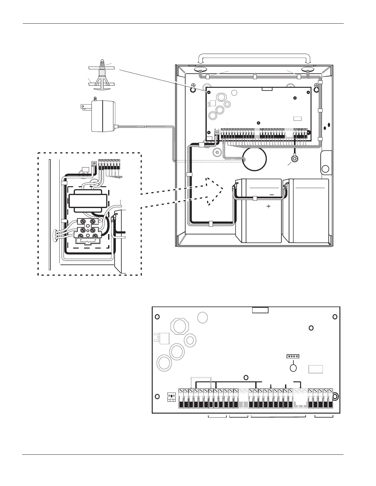
PC Boar d
Cabinet
Stand Of f
Pr imar y:120V A C/60Hz.
Secondar y: 16.5VAC 40VA
DSCPTD 1640U
Class II Tr ansf or mer
NO TE: Do not connect
transf or mer to receptacle
controlled by a s witch
Incorrect connections may result in PTC failure or improper operation.
Inspect wiring and ensure connections are correct be fo re appl ying po we r.
W ARNING:
Incorrect connection of batteries ma y result in batter y rupture or Fire Hazar d.
Do NO T allo w metal objects to connect the Positive and Negative Terminals.
Ensure that batteries are connected with correct polarity [Red to (+), Blac k to (-)].
F ailure to compl y with this ma y result in batte ry rupture and/or Fire Hazar d.
All cir cuits are c lassified fo r UL Installations as Po wer Limited/Class II Power Limited
e xcept fo r battery leads which are not po wer limited.
Do NO T r oute an y wiring o ver cir cuit boar ds .M aintain at least 1"(25.4mm) separation.
A minim um of 1/4" (6.4mm) separation mu st be maintained at all points between
po wer limited wiring and all other non-po wer limited wiring.
1. Inser t Stand off into cabinet
mounting hole in the
desired location. Snap-in-
place .
2. P osition circuit board
mounting holes ov er
standoffs . Press fir mly
on board to snap-in-place .
IMPOR T ANT :
a)This equipment, Alar m Controller PC1616/1832/1864 shal l
be installed and used within an en vironment that pr ov ides th e
pollution degree max 2 and ov er vo ltages categor y II
NON-HAZARDOUS LOCA TIONS , indoor onl y. The equipment is
FIXED and PERMANENTL Y connected and is designed to be
installed by ser vice persons only; [ser vice person is defined as a
person ha ving the appropr iate technical training and e xper ience
necessar y to be aw are of hazards to which that person ma y be
e xposed in per fo r m ing a task and of measures to minimi ze the ri sks
to that person or other persons .]
b)The connection to the mains supply must be made as per the local
author ities ru les and regulations.
An appropr iate disconnect de vice must be pr ov ided as par t of th e
bu ilding installation. Where it is not possi bl e to rely on identification of
the neutral in the AC Mains supply the disconnecting device must
disconnect both poles simultaneously (line and neutral). The device
shall disconnect the supply during servicing.
c)The equipment enclosure must be secured to the bu ilding str uctur e
bef ore operation.
e)Inter nal wi ri ng must be routed in a manner that pr ev ents:
- Excessi ve strain on wire and on te rm inal connections;
- Loosening of te rm inal; connections;
- Damage of conductor insulatio n
f) Disposal of the used batte ri es
shall be made according to the w ast e
reco ve ry and recycling regulations applicab le to the intended mar k et.
CON1
BA T+BA T-
FUSE
AC AC
16.5V /40V A
AC
To EGND
Te r m inal
230 V /50 Hz International
AC
CON1
BA T+BA T-
PO WER LIMITED
NON-PO WER LIMITED
DSC Model BD7-12
or equiv alent
Batter y
Standb yTime:
24H rs min.
BLA CK
RE D
TB-2
AC AC RED BL KY EL GRN Z1 COM Z2 Z3 COM Z4 Z5 COM Z6 Z7 COM Z8
AU X+ BELL +
AU X- BELL-
PGM1 PGM3
EGND
TI PT -1
PGM2 PGM4
RING R- 1
DSC
220 220
UA 50 3
Cab le Tie (not supplied) recommended
PC1864
On ly
PC1864
PC1832
On ly
PC1616/1832/1864
High V oltage .D isconnect AC Po wer
and telephone lines bef ore servicing
W ARNING:
High V oltage . Disconnect AC Po wer
and telephone lines bef ore servicing
W ARNING:
TB-2
DSC
REV XX
220 220
U A503
CON1
BA T+BA T-
PC-LIN K
Internally Connected
AUX+ and Keybus (Red) are Internally Connected
To ta l current draw from Keyp ads, PG MO utput s and
Aux circuit sm ust not exceed 700m A
PC1864
On ly
PC1864
PC1832
Onl y
PC1616/1832/1864
10
12V / 7 AHr 12V / 7 AHr
Nor th America Onl y
See ground wiring
diagram in the Installation
section of this manual
DG009606
Keybus
PGMs
Zones
Telephone
AC AC + AUX - + BELL -
RED BLK YEL GRN
Z1 COM Z2 Z3 COM Z4 Z5 COM Z6 Z7 COM Z8
EGND
RING TIP R-1 T-1
1 PGM 2 3 PGM 4