Chapter 1 Installation & Wiring
1
Chapter 1 Installation & Wiring
This Installation Guide provides the basic installation, wiring and programming information required to program the PowerSeries PC1616,
PC1832, and PC1864 control panels.
All necessary information required to meet UL Listing requirements is included in this document.
Technical Summary
INSTALLATION
FEATURES
PC1616 PC1832 PC1864
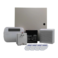
OUT Of THE BOX
On-board Zones 6 8 8
Qty 1
Qty 1
Qty 1
Qty 1
Qty 2
Qty 1
Qty 5
Qty 16
Qty 1
Qty 1
Qty 1
Cabinet
PC Module
Installation Guide
User Manual
Cabinet Label
Cabinet Door Plug
Standoffs
5.6K Resistors
2.2K Resistor
1.0K Resistor
Grounding Kit
Hardwired Zones 16 (1xPC5108) 32(3xPC5108) 64 (7xPC5108)
Wireless Zones 32 32 64
Keypad Zone Support
On-board PGM
Outputs
PGM 1 - 50mA
PGM 2 - 300mA
PGM 1 - 50mA
PGM 2 - 300mA
PGM 1, 3, 4 - 50mA
PGM 2 - 300mA
PGM Expansion
8x50mA (PC5208)
4x500 mA (PC5204)
8x50mA (PC5208)
4x500 mA (PC5204)
8x50mA (PC5208)
4x500 mA (PC5204)
Keypads 8 8 8
Partitions 2 4 8
SPECIFICATIONS
Temp Range . . . 0°C-49°C (32°F-120°F)
Humidity (Max) . . . . . . . . . . . . . 93%R.H.
Power Supply . . 16.5VAC/40VA @60Hz
Current Draw (Panel) . . . .110mA (nom.)
Aux+ Output . . . . 11.1-12.6VDC/700mA
Bell Output. . . . . . 11.1-12.6VDC/700mA
User Codes 47 + Master Code 71 + Master Code 94 + Master Code
Event Buffer 500 Events 500 Events 500 Events
Transformer Required 16.5VAC/40VA 16.5VAC/40VA 16.5VAC/40VA
Battery Required 4Ah / 7Ah/14AHr 4Ah / 7Ah/14AHr 4Ah / 7Ah/14AHr
Bell Output 12V/700 mA (cont) 12V/700 mA (cont) 12V/700 mA (cont)
COMPATIBLE DEVICES
Keypads
(Backward compatible with all PowerSeries keypads) Modules
PK55XX Keypad..............................................................125mA (max.)
RFK55XX Keypad ...........................................................135mA (max.)
LCD5511 Fixed Message LCD Keypad ........................... 85mA (max.)
LED5511Z 8-zone LED Keypad .....................................100mA (max.)
Cabinets
PC5003C......................................... 222x298x78mm (11.3x11.7x3.0in)
PC500C (residential burg only) ......... 213x235x78mm (8.4x9.25x3.0in)
PC4050CAR (UL commercial burg
).. 305x 376x124mm (12.0x14.8x4.9in)
CMC-1 (UL commercial burg) ......... 287x297x76mm (11.3x11.7x3.0in)
Suttle, SAE 14 ......................... 355.6 x 362x 95mm (14x14.25x 3.75in)
Suttle, SAE 21 ......................... 533.4 x 362x 95mm (21x14.25x 3.75in)
Suttle, SAE 28 ......................... 711.2 x 362x 95mm (28x14.25x 3.75in)
Suttle, SAE 42 ....................... 1066.8 x 362x 95mm (42x14.25x 3.75in)
TL-250/TL300 Communicator ............................................ 275/350mA
GS2060/GS2065 (GPRS/GSM only)........................................... 65mA
GS2060-SM (GPRS only) ...........................................................90mA
TL260GS/TL265GS (Ethernet/GPRS) ......................................100mA
TL260-SM (Ethernet only) .........................................................100mA
TL260GS-SM (Ethernet/GPRS only)......................................... 120mA
PC5100 2-wire Interface............... 40mA plus devices to 170mA max.
RF5132-433 Wireless Receiver ...............................................125mA
RF5108-433 Wireless Receiver ...............................................125mA
PC5108 Zone Expander .............................................................30mA
PC5200 Power Supply ................................................................ 20mA
PC5204 Power Supply with 4 Programmable Outputs................ 30mA
PC5208 Low Current Programmable Output Module ................. 50mA
Escort5580 Telephone Interface Module ................................... 130m
*The T-Link TL-150 is not UL/ULC listed
Classified in Accordance with ANSI/SIA CP-01-2000 (SIA-FAR)
Begin the installation by mounting additional modules in the cabinet using the stand-offs provided, then mount the cabinet in a dry, protected
area with access to unswitched AC power. Install hardware in the sequence indicated in the following pages. Do NOT apply power until instal-
lation is complete.
All wiring entry points are designated by arrows. All circuits are classified UL power limited except for the battery leads. Minimum 1/4”
(6.4mm) separation must be maintained at all points between power limited and non-power limited wiring and connections.